The radio itself, as TS 38.300 describes it · chapter 4 of 16 · 7 minutes
4 What NR is — the shape of the 5G radio network
The two kinds of base station, the two interfaces that join them to everything else, and the split of work between the radio network and the core.
Built from §1 §4.1 §4.2 §4.3 §4.5 §4.6 §4.7.1 §4.8 §4.9.1 §5.1 §5.5
4.1 Why there is an overall description at all
The 5G radio is written down across dozens of documents, each owned by a different group and each assuming you already know the shape of the thing. A newcomer reading TS 38.211 first learns about modulation before ever meeting a base station.
TS 38.300 exists to be read first. It says what the pieces are and how they relate, then points at the document that specifies each one §1.
Its scope is narrower than the title suggests. It covers NR — the 5G radio — connected to the 5G core, and says outright that the 4G radio connected to the 5G core is covered in the 36 series instead §1.
4.2 Two kinds of box, and only two
The architecture clause opens with a definition so short it is easy to skim past §4.1:
A gNB speaks the 5G radio to the device. An ng-eNB speaks the 4G radio to the device but is otherwise a full member of the 5G radio network. Both are "NG-RAN nodes" and the rest of the document treats them alike wherever it can.
They are joined to each other by Xn and to the core by NG §4.1. NG splits in two: NG-C to the AMF, the core function that tracks where a device is and whether it can be reached, and NG-U to the UPF, the function that forwards the packets.
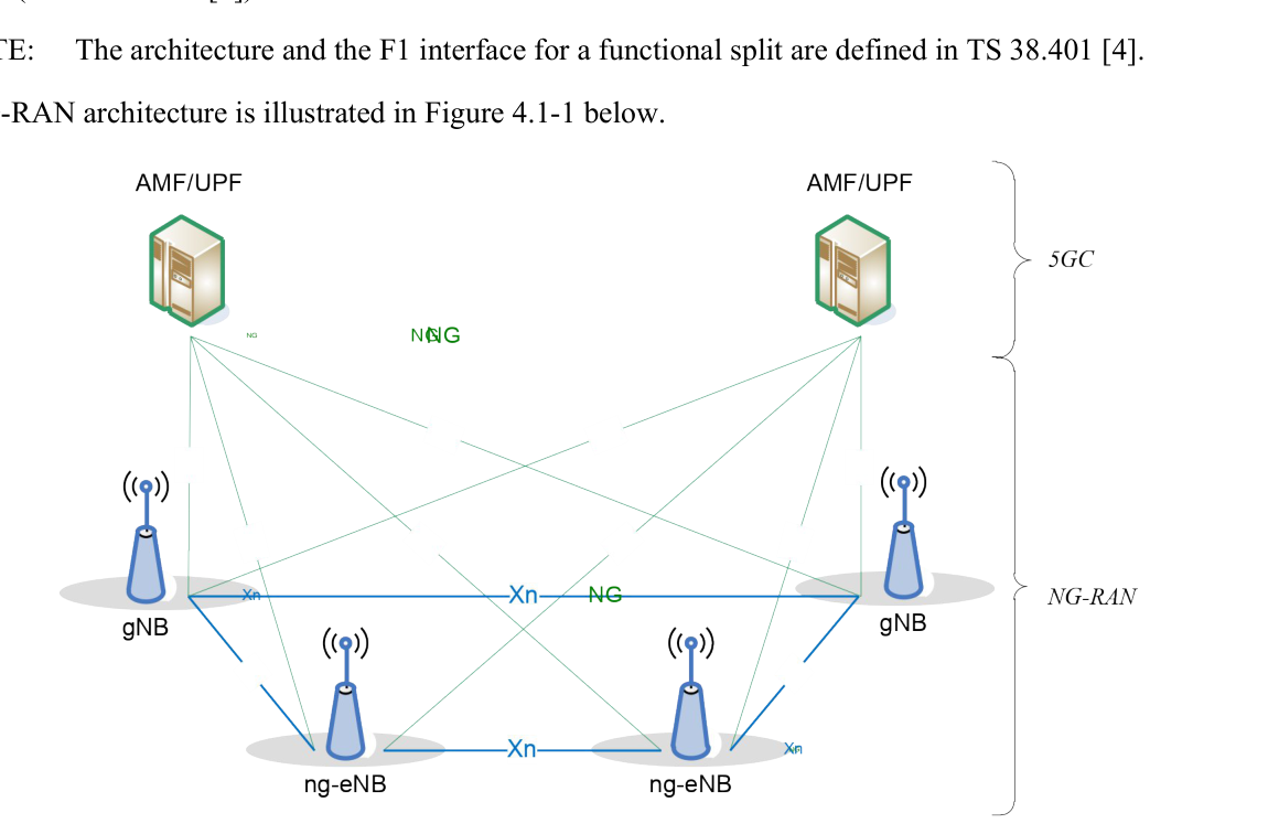
The architecture inside a single node — a base station split into a central part and one or more distributed parts, joined by F1 — is deliberately out of scope here. A note points at TS 38.401 for it §4.1, and that document belongs to RAN3.
4.3 Who does what: the functional split
The functional split clause is a plain list of what a gNB or ng-eNB hosts §4.2. It is the fastest way to see where the radio network's responsibility ends.
The base station hosts, among others:
-
Radio resource management — bearer control, admission control, connection mobility control, and dynamic allocation of resources in uplink, downlink and sidelink. That last one is scheduling.
-
Header compression, encryption and integrity protection of data, in both directions.
-
Selection of an AMF at attachment when nothing the device sent points at one.
-
Routing of user plane data towards the UPF and of control plane information towards the AMF.
-
Connection setup and release, paging, and broadcast of system information.
-
Measurement and measurement reporting configuration for mobility and scheduling.
-
QoS flow management and mapping to data radio bearers, network slicing support, dual connectivity, and support of devices in the inactive state.
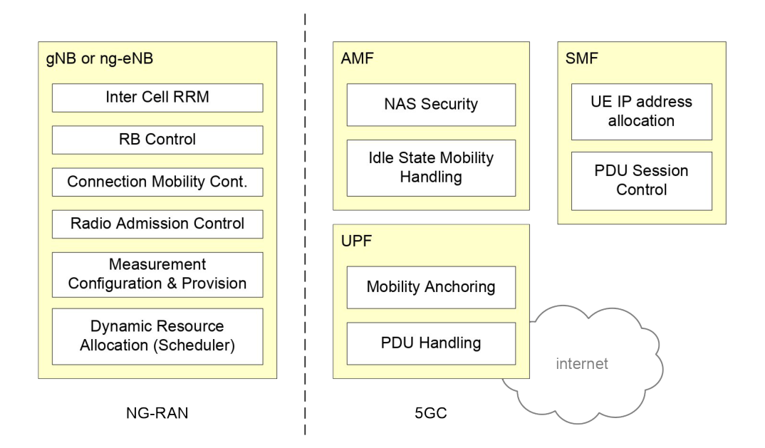
The same clause then lists what the AMF, the UPF and the SMF host, each time with "see TS 23.501" beside it §4.2. That is the document telling you where its own authority stops: it names the core functions so the picture makes sense, and specifies none of them.
4.4 The two interfaces, in one page each
NG-U, the user plane towards the core, runs GTP-U over UDP over IP, and the document is blunt about what it promises: non-guaranteed delivery of user plane packets between the NG-RAN node and the UPF §4.3.1.1.
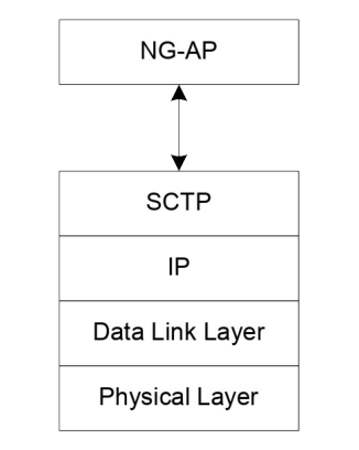
NG-C, the control plane towards the core, runs a protocol called NGAP over SCTP over IP, and SCTP is what gives it guaranteed delivery §4.3.1.2. Its functions are interface management, device context management, device mobility management, transport of core network messages, paging, session management, configuration transfer and warning messages.
Xn-U, between two NG-RAN nodes, is GTP-U again and does two things: data forwarding and flow control §4.3.2.1.
Xn-C runs XnAP over SCTP and does three: interface management, device mobility management including context transfer and paging, and dual connectivity §4.3.2.2.
Each of the four clauses ends by naming the document that specifies it — TS 38.410 for NG, TS 38.420 for Xn. Both are RAN3's.
4.5 The radio itself, in two clauses
The waveform clause is the densest page in the document §5.1. Downlink is ordinary OFDM with a cyclic prefix. Uplink is the same, with a transform that spreads the signal across sub-carriers and can be switched on or off.
The numerology is a single formula: sub-carrier spacing is 2^µ × 15 kHz. Twelve consecutive sub-carriers make a physical resource block, and up to 275 of them fit on one carrier §5.1.
Time is divided into frames of 10 ms, each ten subframes of 1 ms, each divided into slots of 14 symbols with the normal cyclic prefix §5.1. Because the slot scales with the sub-carrier spacing, a subframe always holds a whole number of slots.
That is the whole trick of NR's flexibility: one formula, one frame length, and everything else follows from µ.
The transport channel clause §5.5 then says what the physical layer offers upwards. Down: the broadcast channel, the downlink shared channel and the paging channel. Up: the uplink shared channel and the random access channel. Sidelink — device to device — has its own two.
4.6 The four architectures bolted on the side
Clause 4 does not stop at the basic picture. Four more architectures are defined in the same clause, each a variation on where the radio actually is.
Multi-radio dual connectivity §4.5: a connected device uses radio from two schedulers in two different NG-RAN nodes joined by an imperfect link, one of them NR and the other E-UTRA or NR. The detail is TS 37.340.
Radio access network sharing §4.6: one cell broadcasts a tracking area code and a cell identity for each subset of networks sharing it.
Integrated access and backhaul §4.7.1: a relay node that uses NR itself as its backhaul, calling the terminating node an IAB-donor and allowing multiple hops.
Network-controlled repeaters §4.9.1: a radio-frequency repeater that amplifies and forwards, but takes side control information from the base station over a control link so the network knows what it is doing.
There is also a clause for non-public networks §4.8 — networks not open to the general public, either standing alone or riding on a public one.
4.7 Where this meets the rest of the course
What sits between the physical layer and the core, sublayer by sublayer, is The radio protocol stack, sublayer by sublayer. What the device is doing when it is not connected is The three states a device sits in.
The two interfaces sketched here are opened properly in Where the radio network meets the core, and the groups that own each document named on this page are The six working groups, and where the line between them runs.
Check yourself
Answers appear when you pick one, with where they come from.
Q4.1 Which two interfaces join an NG-RAN node to the rest of the world?
The architecture clause says gNBs and ng-eNBs are interconnected by Xn and connected to the 5GC by NG — NG-C to the AMF and NG-U to the UPF. §4.1
Q4.2 What selects the AMF when a device attaches and nothing in what it sent points at one?
Selecting an AMF at attachment, when no routing to one can be worked out from what the device provided, is on the list of functions the base station hosts. §4.2
Q4.3 How does the sub-carrier spacing of NR scale?
The numerology clause gives the spacing as 2^µ × 15 kHz, with the allowed values of µ listed separately for synchronisation and for everything else. §5.1
Q4.4 How many physical resource blocks fit on one carrier at most?
Twelve consecutive sub-carriers make one physical resource block, and the clause says up to 275 of them are supported on a carrier. §5.1
Q4.5 What is the difference between a transport channel and a logical channel?
The clause on transport channels says so directly, and warns that the two must be kept apart. §5.5
This chapter was written against TS 38.300 version 19.3.0, and built from a source register generated 2026-08-04. A newer version of the document may say something else.