The radio itself, as TS 38.300 describes it · chapter 5 of 16 · 8 minutes
5 The radio protocol stack, sublayer by sublayer
What MAC, RLC, PDCP, SDAP and RRC each do, what each one hands to the next, and which document specifies each of them.
Built from §4.4.1 §4.4.2 §6.1 §6.2 §6.3 §6.4 §6.5 §6.6 §6.7 §6.8 §6.10 §7.1 §10.1
5.1 Why there is a stack at all
An IP packet arriving for a phone has to be turned into something a radio can send: cut into pieces small enough for one transmission, numbered so a lost piece can be spotted, encrypted, mixed with other packets for the same device, and handed to a transmitter with a modulation and a coding rate.
No single piece of software should do all of that, because each step has a different reason to change. Encryption changes when cryptography changes. Segmentation changes when the radio changes. Mapping traffic to a quality class changes when the core network changes.
So NR splits the work into four sublayers with defined services between them, and puts a fifth protocol beside them for control. Each has its own document and, above the physical layer, its own owning group.
5.2 The chain of services
The layer-2 overview states the chain in five lines §6.1: the physical layer offers transport channels to MAC; MAC offers logical channels to RLC; RLC offers RLC channels to PDCP; PDCP offers radio bearers to SDAP; and SDAP offers QoS flows to the core network.
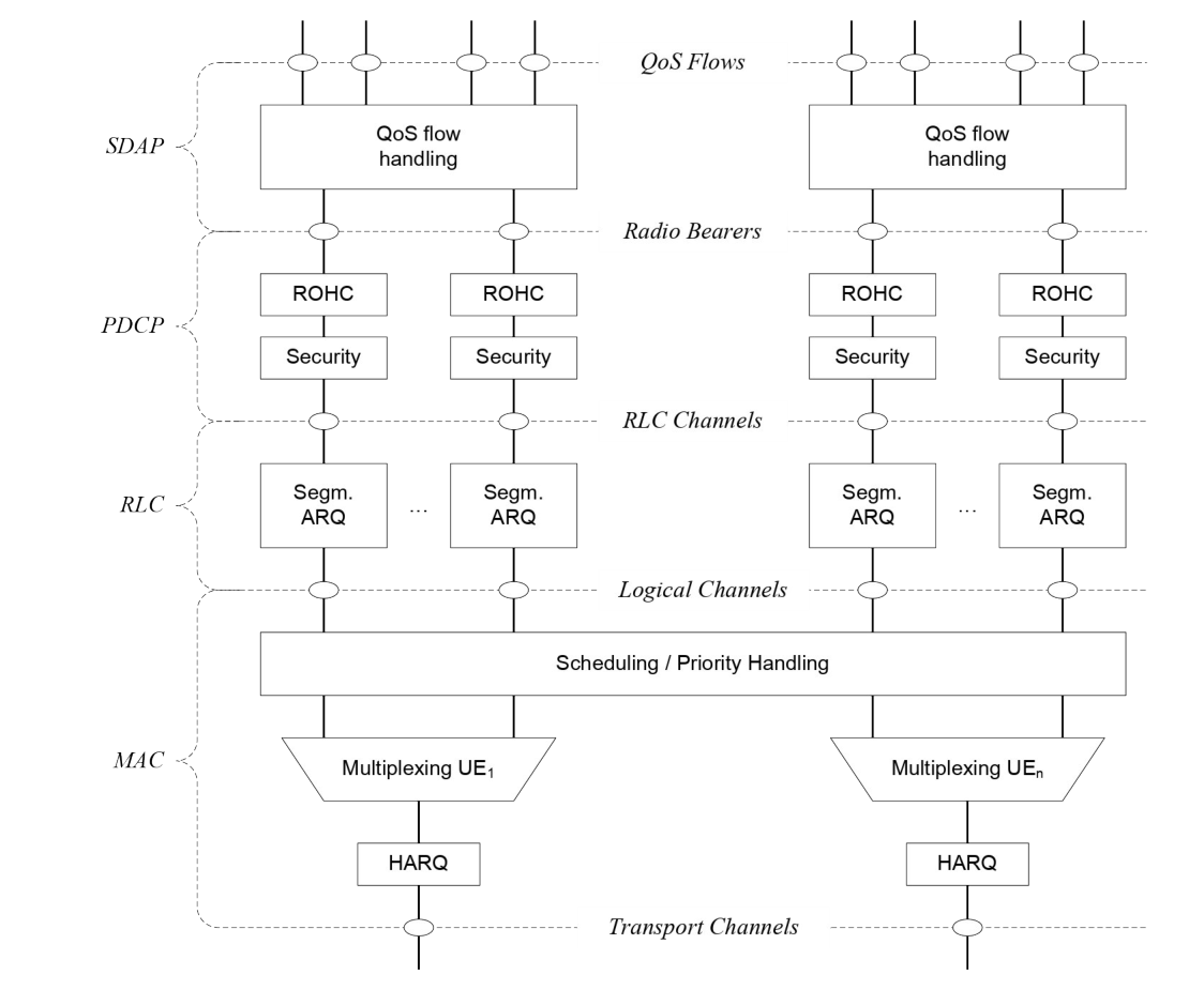
Radio bearers come in two kinds: data radio bearers for user traffic and signalling radio bearers for control §6.1.
The control plane stack is the same minus one sublayer. SDAP is not there, because control messages have no QoS flow; instead RRC sits on PDCP, and above RRC sits NAS — the core network's own conversation with the device, which the radio network carries but never reads §4.4.2.
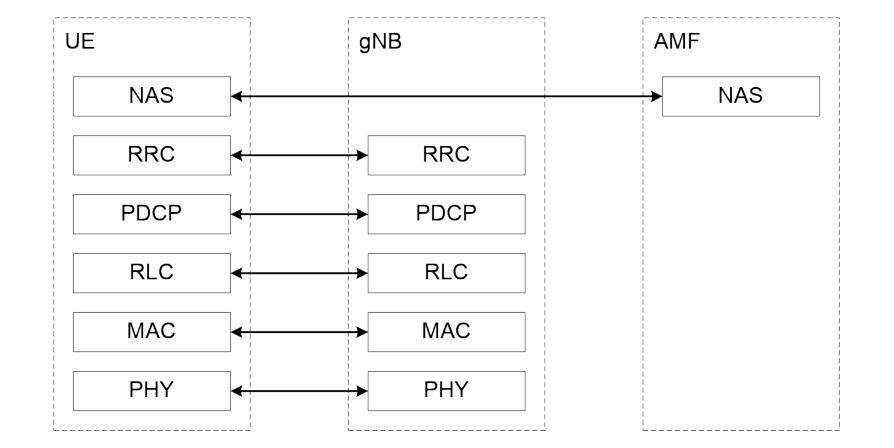
The user plane stack is SDAP, PDCP, RLC and MAC, all terminated in the gNB on the network side §4.4.1.
5.3 MAC — scheduling, multiplexing and retransmission
MAC's service list §6.2.1 is short and every item earns its place:
-
mapping logical channels to transport channels;
-
multiplexing and demultiplexing;
-
scheduling information reporting;
-
error correction through HARQ;
-
priority handling between devices, between one device's logical channels, and between overlapping resources;
-
padding.
HARQ is hybrid automatic repeat request: a failed transmission is repeated and the receiver combines the attempts rather than throwing the first one away. There is one HARQ entity per cell when carriers are aggregated §6.2.1, and a HARQ process carries one transport block, or several when spatial multiplexing is configured §6.2.4.
The logical channels themselves are five §6.2.2. Four carry control: BCCH for broadcast system information, PCCH for paging, CCCH for devices with no connection yet, and DCCH for devices that have one. One carries traffic: DTCH, point to point, in both directions.
The mapping to transport channels is fixed and worth memorising §6.2.3. Downlink: BCCH to BCH or DL-SCH, PCCH to PCH, CCCH and DCCH and DTCH all to DL-SCH. Uplink: CCCH, DCCH and DTCH all to UL-SCH.
The schedulers live here, in MAC in the gNB §10.1.
They assign resources between devices taking account of buffer status and quality requirements, and they are told what to work with by two measurements the device sends up: buffer status reports, saying how much is queued, and power headroom reports, saying how much transmit power is left.
5.4 RLC — three modes and one job
RLC has three transmission modes and the choice of mode is per logical channel §6.3.1:
Transparent mode adds nothing. Unacknowledged mode numbers and segments but never retransmits. Acknowledged mode does retransmit, and only acknowledged mode gets duplicate detection and protocol error detection §6.3.2.
Its retransmission machinery, ARQ, works on whole packets or on segments of them, driven by status reports §6.3.3. The transmitter can poll for a status report; the receiver can also send one unprompted when it notices a gap.
5.5 PDCP — where the security is
PDCP's list is the longest of the four §6.4.1:
-
transfer of data, and PDCP sequence numbers;
-
header compression by two different schemes, and uplink data compression;
-
ciphering and integrity protection;
-
timer-based discard, and routing for split bearers;
-
duplication, duplicate discarding, reordering, in-order delivery and out-of-order delivery.
Two of those are the whole reason the sublayer exists where it does. Ciphering and integrity protection sit above segmentation, so the same protected packet survives being cut up differently on a retransmission.
And reordering sits above the retransmitting layer, so what comes out is in order even though what went in came back out of order.
The clause ends with a constraint that catches implementers: PDCP does not allow its counter to wrap around, so the network has to stop that happening — by releasing and re-adding the bearer, or by a full reconfiguration §6.4.1.
5.6 SDAP — the thinnest sublayer
SDAP does two things §6.5: it maps a QoS flow to a data radio bearer, and it marks the QoS flow identifier in packets in both directions.
That is the entire service list, and it is the seam between the radio network and the core. What a QoS flow is, and where the mapping rules come from, is Where the radio network meets the core.
One entity per PDU session, no more and no less §6.5.
5.7 What flows through it
The data flow example is the one figure worth studying §6.6: a transport block built by MAC out of two RLC packets from one bearer and one RLC packet from another, where the third is a segment of a larger IP packet.
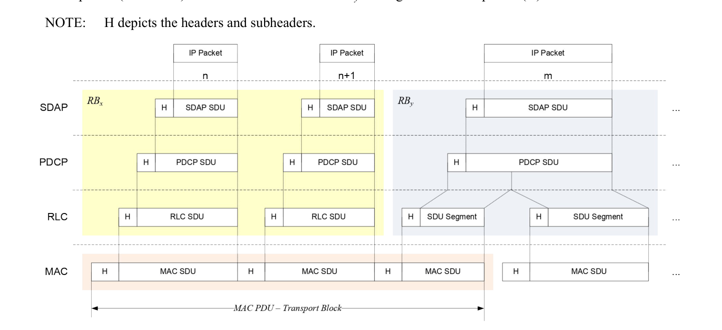
Each sublayer adds a header, and the picture makes the cost visible. It is also the answer to the commonest sizing question: the size of a transport block is a physical layer decision, so segmentation happens because of the radio, not because of the traffic.
5.8 The three configurations that change the picture
Carrier aggregation §6.7: several carriers serve one device. The multi-carrier nature is exposed only to MAC, which needs one HARQ entity per serving cell. Each transport block and its retransmissions stay on one cell.
Dual connectivity §6.8: two cell groups, and therefore two MAC entities in the device — one for each group. The detail lives in TS 37.340.
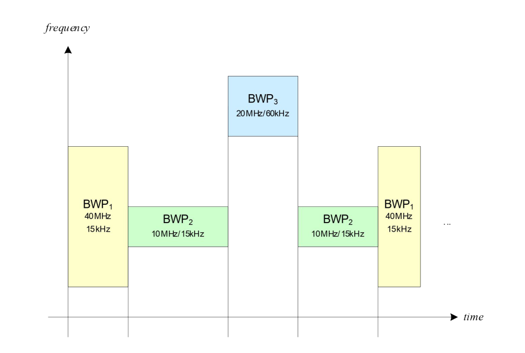
Bandwidth adaptation §6.10: the device's transmit and receive bandwidth need not be the cell's. A bandwidth part is a subset of the cell bandwidth, and the network tells the device which configured part is active.
The width can be ordered to shrink when there is little traffic, the position can move in frequency, and the sub-carrier spacing can change §6.10. The worked example in the clause has three parts configured: 40 MHz at 15 kHz, 10 MHz at 15 kHz and 20 MHz at 60 kHz.
5.9 RRC — the control protocol on top
RRC is layer 3, and its service list §7.1 is the shape of everything a connection needs over its lifetime:
-
broadcast of system information, and paging;
-
establishment, maintenance and release of the connection;
-
security functions including key management;
-
establishment of signalling and data bearers;
-
mobility, including handover and cell reselection;
-
quality of service management, and measurement reporting;
-
detection of and recovery from radio link failure;
-
transfer of the core network's own messages.
Two of those deserve their own chapter each: the states RRC defines are The three states a device sits in, and setting up and moving a connection is How a connection is set up, and how it is moved.
5.10 Which document specifies which sublayer
| Sublayer | Document | Owner |
|---|---|---|
| Physical layer | TS 38.211, TS 38.212, TS 38.213, TS 38.214 | RAN1 |
| MAC | TS 38.321 | RAN2 |
| RLC | TS 38.322 | RAN2 |
| PDCP | TS 38.323 | RAN2 |
| RRC | TS 38.331 | RAN2 |
SDAP has its own document too, and the backhaul adaptation protocol used by relay nodes is TS 38.340 — also RAN2's.
That is the practical meaning of the split described in The six working groups, and where the line between them runs: one seam in this table, between the physical layer and MAC, is also the seam between two working groups. Everything above it is argued in one room.
5.11 Where this meets the rest of the course
What the device is doing when none of this is running is The three states a device sits in. How the stack is brought up in the first place is How a connection is set up, and how it is moved. What SDAP is mapping, and where the mapping rules come from, is Where the radio network meets the core.
Check yourself
Answers appear when you pick one, with where they come from.
Q5.1 Which sublayer does the ciphering of user data?
Ciphering and deciphering, integrity protection and verification, and header compression are all in the PDCP service list. §6.4.1
Q5.2 Which RLC transmission mode is used for signalling radio bearer 0, paging and broadcast system information?
The clause says transparent mode for SRB0, paging and broadcast system information; acknowledged mode for other signalling bearers; and either unacknowledged or acknowledged for data bearers. §6.3.1
Q5.3 How many SDAP entities does a device have?
The clause says a single protocol entity of SDAP is configured for each individual PDU session. §6.5
Q5.4 What is a bandwidth part?
Bandwidth adaptation configures the device with bandwidth parts and tells it which one is active; the width, the position in frequency and the sub-carrier spacing can all be changed. §6.10
Q5.5 Where do the schedulers live?
The scheduling clause says MAC in the gNB includes dynamic resource schedulers that allocate physical layer resources for downlink and uplink. §10.1
Q5.6 In carrier aggregation, what does the multi-carrier nature of the physical layer get exposed to?
The clause says the multi-carrier nature is only exposed to MAC, which is why there is one independent hybrid-ARQ entity per serving cell. §6.7
This chapter was written against TS 38.300 version 19.3.0, and built from a source register generated 2026-08-04. A newer version of the document may say something else.