The radio itself, as TS 38.300 describes it · chapter 7 of 16 · 9 minutes
7 How a connection is set up, and how it is moved
Random access, connection setup, resume, measurement, handover and what happens when a handover fails.
Built from §7.3.2 §9.1 §9.2.1.3 §9.2.2.4.1 §9.2.2.4.2 §9.2.3.1 §9.2.3.2.1 §9.2.3.3 §9.2.3.4.1 §9.2.4 §9.2.6 §9.2.7
7.1 Why getting on the air is a procedure at all
A device that wants to talk has a problem no wired network has: it does not know when it may transmit, and neither does anybody else. Every device in the cell shares one uplink, and none of them is synchronised until somebody tells it how far away it is.
So the first thing that happens is always the same, whatever the reason: the device picks a preamble out of a known set, sends it, and waits to be told when to speak next. That is random access, and every other procedure in this chapter sits on top of it.
7.2 Random access: two shapes, two flavours
The clause lists every trigger §9.2.6.
The obvious ones — initial access from idle, resume from inactive, handover, re-establishment — are joined by data arriving when the uplink is out of sync, a scheduling request failing, beam failure recovery, a request for other system information, positioning, and several more.
There are two types §9.2.6:
-
Four-step, where MSG1 is a preamble on PRACH, MSG2 is the response, MSG3 is sent on the grant that response carried, and MSG4 resolves contention.
-
Two-step, where MSGA carries the preamble and a payload together and MSGB is the response.
And two flavours, crossed with the types:
-
Contention-based, where the preamble is chosen from a shared set and two devices may pick the same one — hence the contention resolution step.
-
Contention-free, where the network has assigned this device a preamble of its own, so the procedure ends as soon as the response arrives.
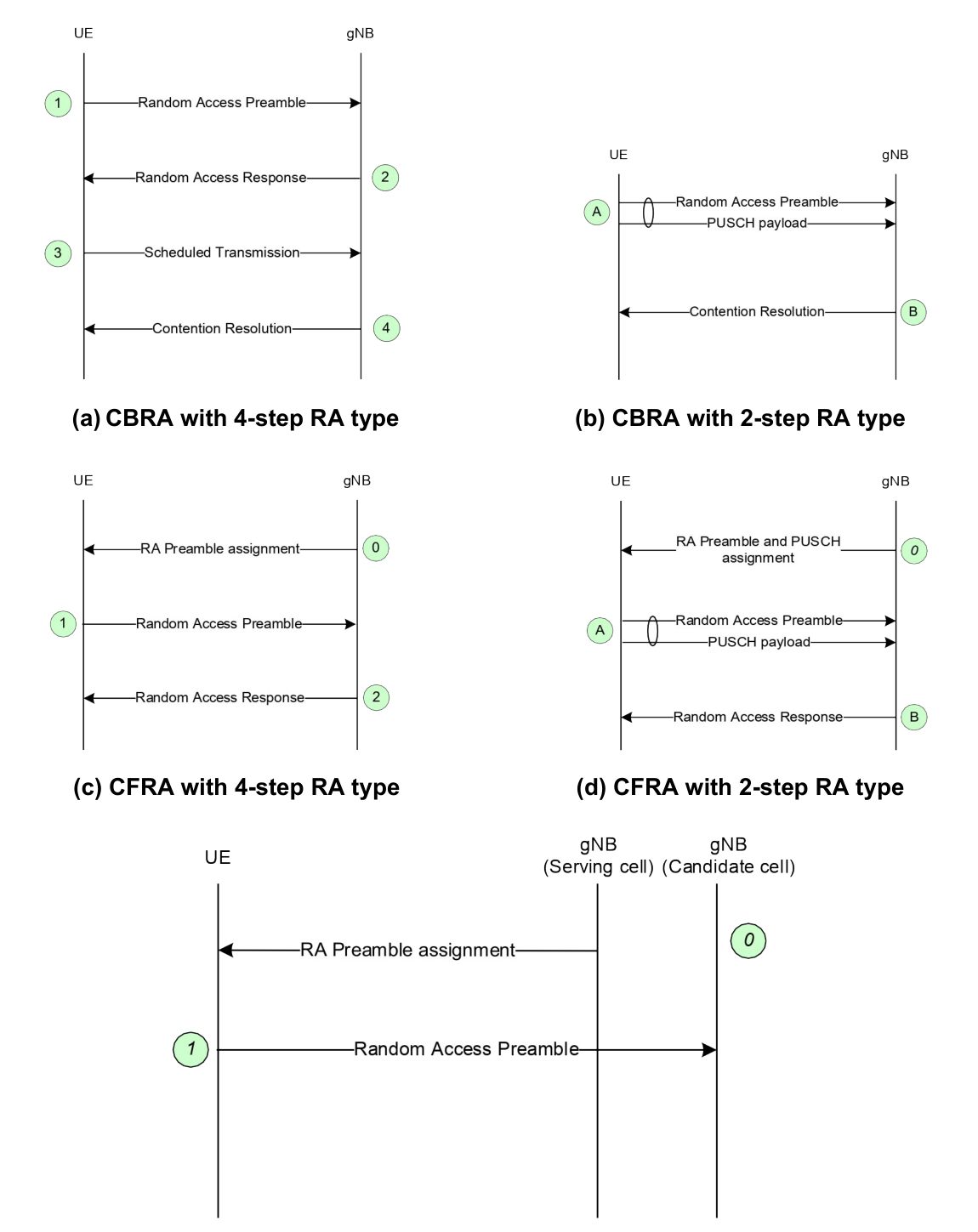
How the device chooses is decided by configuration §9.2.6. Where no contention-free resources are configured, a signal-strength threshold decides between two-step and four-step. Where contention-free resources are configured for one of the types, that type is used.
The network never configures contention-free resources for both types on the same bandwidth part at once, and contention-free two-step is only used for handover.
If two-step does not complete after a number of attempts, the device can be configured to fall back to contention-based four-step §9.2.6.
7.3 From idle to connected
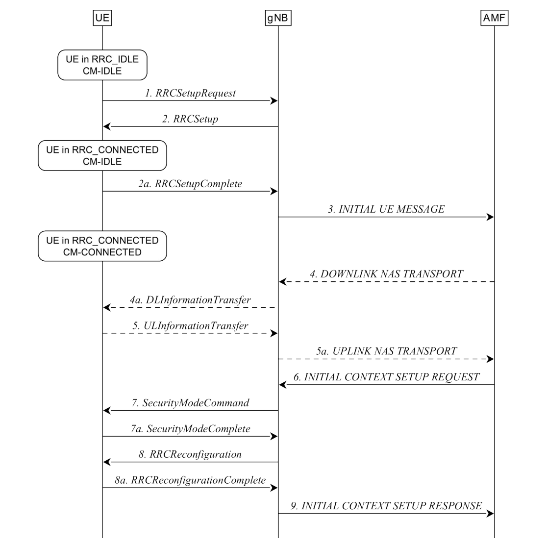
The setup flow §9.2.1.3 is worth walking through, because every later flow is a shortened version of it. The numbers in the figure are the document's; the description below follows them in order.
-
The device asks to set up a connection, and the base station completes the RRC setup.
-
The first core-network message, carried inside the setup-complete message, goes to the AMF, and further core-network messages may pass in both directions.
-
The AMF prepares the device context — session context, security key, radio capability, security capabilities — and sends it to the base station.
-
The base station activates access-stratum security with the device.
-
The base station reconfigures the device to set up the second signalling bearer and the data bearers. For a signalling-only connection this step is skipped.
-
The base station tells the AMF the setup is done.
The notes on that flow carry the security story §9.2.1.3: the first two messages use signalling bearer 0, everything after uses bearer 1, the security activation messages are integrity protected, and from the reconfiguration onwards everything is integrity protected and ciphered.
The network can also refuse. If the base station cannot handle the request — the clause gives congestion as the example — it sends a reject with a wait time and the device stays where it was §9.2.1.3.
7.4 From inactive to connected
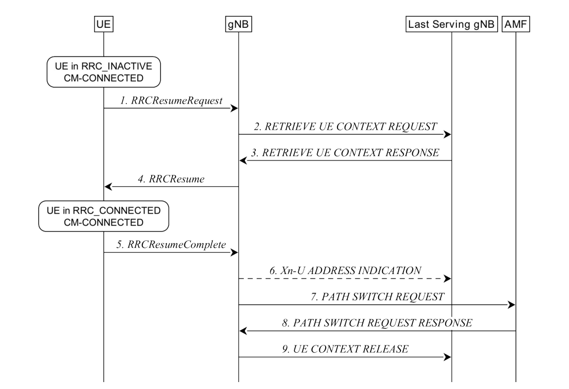
Resuming is the same shape with the expensive middle removed §9.2.2.4.1.
The device sends its I-RNTI. The base station resolves which node allocated it and asks that node for the context over Xn.
The context arrives, the connection is resumed in two more messages, forwarding addresses are exchanged if buffered downlink data must not be lost, the path is switched at the core network, and the old node's resources are released.
Two failure paths matter.
If the last serving node cannot retrieve or verify the context, it says so, and the new base station falls back to setting up a fresh connection instead §9.2.2.4.1. The clause is explicit that this also happens if the serving AMF has changed.
If the base station is congested it rejects, with a wait time, and the device stays inactive §9.2.2.4.1.
The network can start the same thing from its side: a paging trigger occurs, RAN paging goes out in the last serving node's cells and over Xn to the others in the notification area, the device is paged with its I-RNTI, and if it hears it, it resumes exactly as above §9.2.2.4.2.
7.5 Measurement: what the device is watching
Handover in connected mode is the network's decision, and the input is the device's measurement report. The measurement model is a chain of named points §9.2.4.
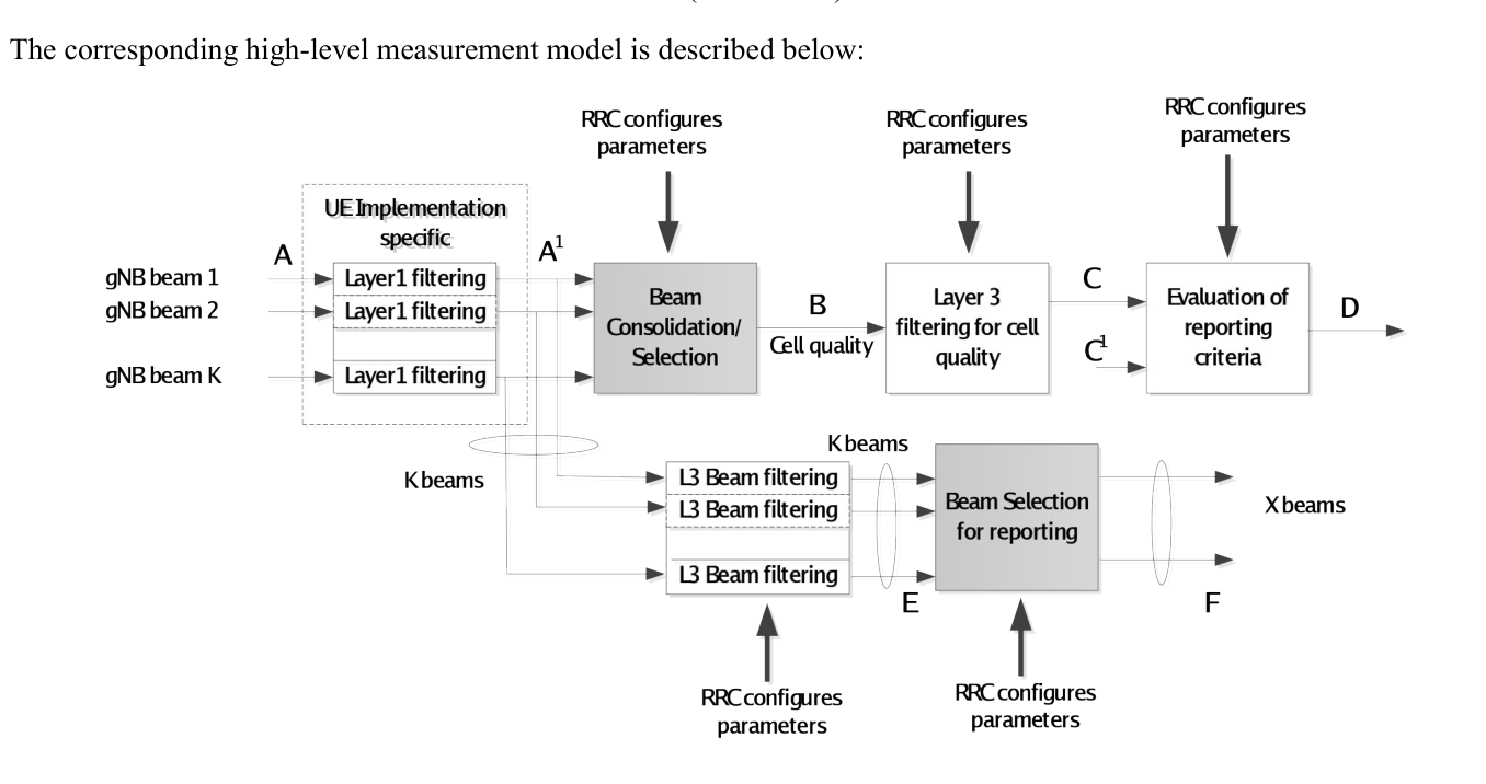
The device measures several beams of a cell. The physical layer filters them into a beam quality. Beam consolidation turns several beams into one cell quality. RRC-level filtering smooths that.
The reporting criteria are then evaluated against the filtered value, and only then is a report sent §9.2.4.
Which parts of that are standardised is the interesting bit. Layer 1 filtering is implementation dependent and explicitly not constrained. Beam consolidation, layer 3 filtering and the reporting criteria are all standardised and all configured by RRC §9.2.4.
How well the device has to measure — how fast, how accurately — is not in this document at all. The clause points at TS 38.133, which is RAN4's §9.2.4.
The measurement configuration itself is built from three things §9.1: a measurement object, which says what to measure; a reporting configuration, which says when to report; and a measurement identity that ties one of each together.
Several identities let one object feed several reports, or one report serve several objects.
7.6 Handover, step by step
The overview gives the four bones of an inter-base-station handover §9.2.3.1: the source sends a handover request over Xn; the target does admission control and returns a new configuration in its acknowledgement; the source forwards that configuration; the device moves and replies.
The full flow adds the core network §9.2.3.2.1:
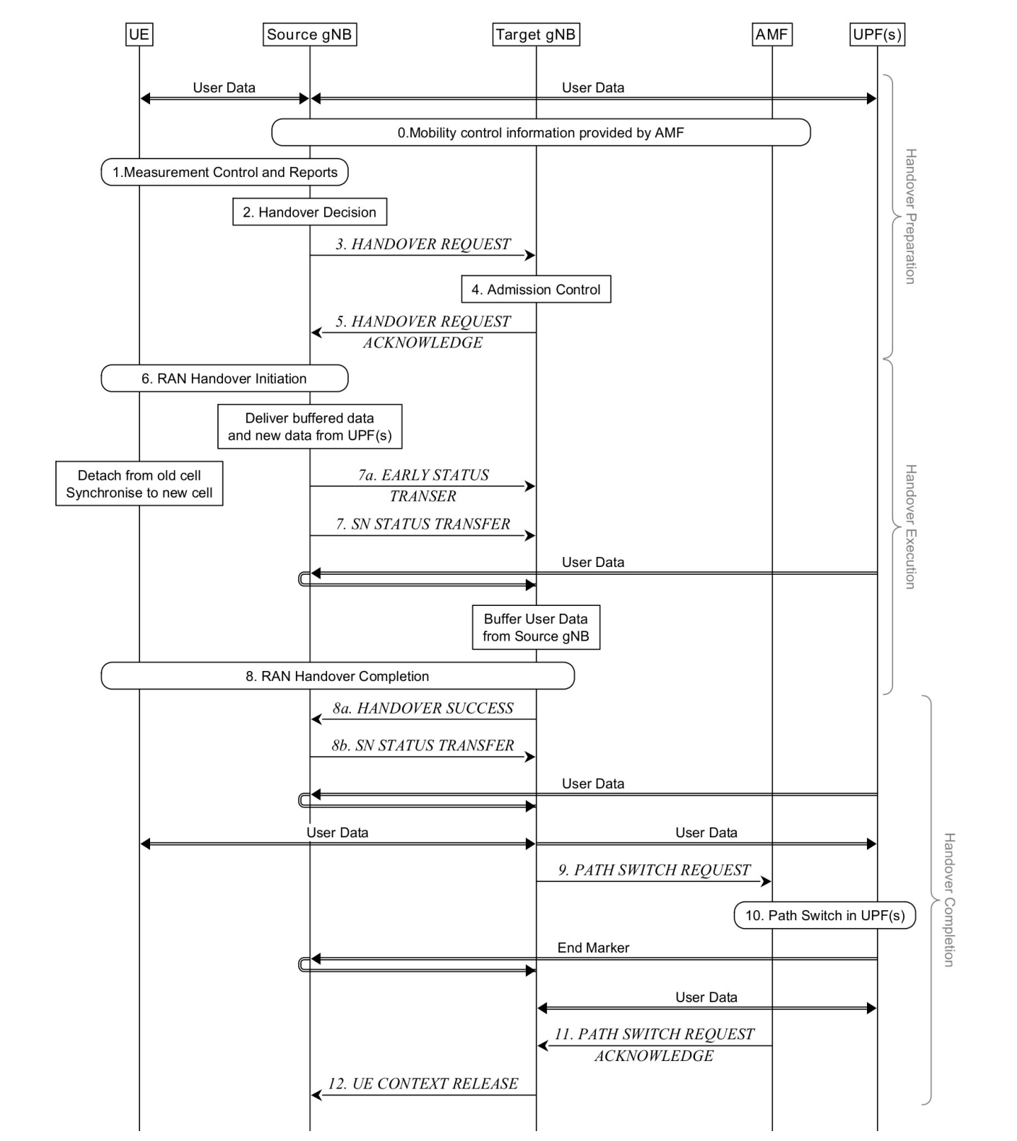
The source configures measurements and the device reports. The source decides, on the report and its own radio information.
The handover request carries the target cell identity, a derived key and the device's current identity in the source cell.
It also carries the radio configuration, the current mapping of QoS flows to bearers, the source's own system information, the device's capabilities and the session information including slices.
The target performs admission control — slice-aware, and it rejects sessions whose slices it does not support — and prepares the handover at layers 1 and 2.
The source then sends the reconfiguration to the device, containing the target cell identity, the new device identity, the target's security algorithm identifiers, and possibly dedicated random access resources and the target's system information.
The device synchronises to the target and completes. The target asks the AMF to switch the downlink path; the core switches it, and the user plane function sends end-marker packets down the old path so the target knows the old one is drained.
The AMF confirms, and the target tells the source to release the context.
7.7 When the network prepares more than one target
Conditional handover hands the decision to the device §9.2.3.4.1. The configuration carries candidate cells prepared by the candidate base stations, plus execution conditions written by the source. The device evaluates the conditions from the moment it receives them and executes when one is met.
An execution condition may be one or two triggers, at most two different measured quantities at once, and only one kind of reference signal §9.2.3.4.1.
Two constraints in that clause save a lot of confusion. An ordinary handover command overrides any conditional configuration already held. And once the device starts synchronising with the target, it stops monitoring the source §9.2.3.4.1.
7.8 When it goes wrong
Radio link failure is declared on any of six conditions §9.2.7: a radio problem timer expiring, a timer started on a measurement report expiring while a radio problem timer runs, random access failing, RLC failing, consistent uplink listen-before-talk failures in shared spectrum, or — for a relay node — a backhaul failure indication from its parent.
After declaring it, the device stays in RRC_CONNECTED, selects a suitable cell and starts re-establishment; if it finds no suitable cell within a certain time it goes to RRC_IDLE §9.2.7.
Where a conditional handover was configured, it may instead try one conditional execution, if the selected cell is a candidate and the network allowed it §9.2.7.
Re-establishment itself is a short flow §9.2.3.3: the device offers its old identity — the physical cell identity plus its old radio identity — to whichever base station it landed on; that node fetches the context from the last serving one if it does not have it; the connection is continued on signalling bearer 1, bearers are restored, data is forwarded, and the path is switched.
7.9 Where this meets the rest of the course
The states these flows move between are The three states a device sits in. The protocol layers each message travels through are The radio protocol stack, sublayer by sublayer. The path switch at the end of a handover, and the keys derived along the way, are Where the radio network meets the core.
The Xn messages themselves are specified by RAN3 in TS 38.423, and the RRC messages by RAN2 in TS 38.331 — one procedure, two groups, as The six working groups, and where the line between them runs describes.
Check yourself
Answers appear when you pick one, with where they come from.
Q7.1 In the four-step random access procedure, what is in MSG1?
MSG1 of the four-step type is a preamble on PRACH. The two-step type sends a preamble and a payload together, as MSGA. §9.2.6
Q7.2 Which node decides that a handover should happen?
Step 2 of the handover procedure is the source gNB deciding, based on the MeasurementReport and RRM information. The device measures and reports; it does not decide. §9.2.3.2.1
Q7.3 What is a conditional handover?
The device starts evaluating the execution conditions when it receives the configuration and executes the handover when one is met. The candidate configurations come from the candidate base stations, the conditions from the source. §9.2.3.4.1
Q7.4 Where does the device get the information it needs to access the target cell during a handover?
The message includes at least the cell identity and everything needed to access the target cell, so the device can get in without reading system information. §9.2.3.1
Q7.5 What does the device do first after declaring radio link failure in the ordinary case?
The device stays in RRC_CONNECTED, selects a suitable cell and starts re-establishment, and only enters RRC_IDLE if no suitable cell is found within a certain time. §9.2.7
Q7.6 At which two levels is a measurement filtered before it can trigger a report?
Filtering happens at the physical layer to derive beam quality and then at RRC level to derive cell quality from multiple beams. §9.2.4
This chapter was written against TS 38.300 version 19.3.0, and built from a source register generated 2026-08-04. A newer version of the document may say something else.