The radio itself, as TS 38.300 describes it · chapter 6 of 16 · 8 minutes
6 The three states a device sits in
Idle, inactive and connected — what the network remembers in each, who pages, and why the middle state was invented.
Built from §7.2 §8.1 §9.2.1.1 §9.2.1.2 §9.2.2.1 §9.2.2.3 §9.2.5 §11 §13.3 §18.0 §Annex C §Annex F
6.1 The problem the middle state solves
A phone that is doing nothing should cost the network nothing and the battery almost nothing. A phone that starts doing something should be back on the air in milliseconds.
Those two wishes fight. Tearing a connection down completely saves resources but makes coming back expensive: authentication, key derivation, bearer setup, a message to the core network. Keeping it up is instant but expensive to hold.
4G had only the two extremes. NR adds a third state in between, where the connection is suspended rather than released: the radio is quiet, but the context is still sitting at the base station that last served the device.
6.2 What the document says each state is
The protocol states clause is a bare list, one bullet per property §7.2. Read side by side, the three lists differ in exactly the places that matter.
| RRC_IDLE | RRC_INACTIVE | RRC_CONNECTED | |
|---|---|---|---|
| Who pages | the 5G core | the radio network | not paged for data |
| Mobility | cell reselection, by the device | cell reselection, by the device | network controlled, with measurements |
| Core connection | none | established, both planes | established, both planes |
| Context stored | no | in the radio network and the device | in the radio network and the device |
| Network knows | nothing | the notification area | the cell |
| Sleep cycle set by | the core, through NAS | the radio network | connected-mode DRX |
Three things follow from that table and are worth saying out loud.
The core network cannot tell RRC_INACTIVE from RRC_CONNECTED. The connection to the AMF and the UPF exists in both. That is the entire point: the saving is inside the radio network.
The device does its own mobility in two of the three states. Reselection is the device's decision in idle and inactive; handover is the network's decision in connected §7.2.
Only the granularity of what the network knows changes. Nothing, the notification area, the cell.
6.3 RRC_IDLE — camping
A device in idle has to find a cell to camp on. Cell selection happens on transition into the state and on recovery from being out of coverage, and it is always based on the synchronisation signal blocks that sit on the synchronisation raster §9.2.1.1.
The device searches the frequency bands, finds the strongest cell on each carrier, and reads its broadcast information to see which networks it serves. It may search each carrier in turn — "initial cell selection" — or use stored information to shorten the hunt §9.2.1.1.
Then it applies a two-level test §9.2.1.1:
-
A suitable cell passes the measurement criteria, belongs to the selected, registered or an equivalent network, is not barred or reserved, is not in a forbidden tracking area, and uses an access technology the device is allowed to use.
-
An acceptable cell only passes the measurement criteria and is not barred. It is the fallback, and it is what emergency calls run on.
Once camped, the device keeps reselecting §9.2.1.2. Reselection within a frequency is a ranking of cells; reselection between frequencies is by absolute priority, so the device tries to sit on the highest-priority frequency available.
The serving cell can steer that with a neighbour cell list, exclude-lists, allow-lists, speed dependence, service-specific priorities, cell-type-specific priorities and slice-based reselection information §9.2.1.2.
6.4 RRC_INACTIVE — suspended
In inactive, the device stays in the core network's connected state and can move around inside an area the radio network gave it without saying anything §9.2.2.1. The last serving base station keeps the context and keeps the device-associated connection with the AMF and the UPF.
When downlink data or downlink signalling arrives for a device in this state, that base station pages in the cells of the notification area, and if the area covers cells belonging to neighbouring base stations it asks them to page too, over Xn §9.2.2.1.
The area itself is the RAN-based notification area §9.2.2.3. It can be a list of cells given to the device explicitly, or a list of RAN areas, where a RAN area is a subset of a core-network tracking area or the whole of one. The area must fit inside the core network's registration area.
The device sends a notification area update periodically, and whenever reselection picks a cell outside the area §9.2.2.3. The network may use different kinds of area definition for different devices, but never two kinds for the same device at the same time.
The AMF helps the base station decide whether a device should be sent to this state at all, by sending Core Network Assistance Information §9.2.2.1:
-
the registration area, and the periodic registration timer;
-
the device's sleep cycle and its identity index;
-
whether the device is in mobile-initiated-only mode, and its expected behaviour;
-
its radio capability for paging, and several paging subgroup hints.
6.5 The identity that makes it work
Resuming from inactive at a different base station only works if the new one can find the old one. That is what the I-RNTI is for: a reference to the device context and to the node that allocated it §Annex F.
Its structure is fixed §Annex F: a profile identifier at the top, then a local node identifier, then the reference to the context stored in that node. The profile says how long the node identifier is.
§Annex C gives three worked partitions of a 40-bit I-RNTI, trading device references against node addresses — 20 bits and 20 bits, or 20 and 16 with 4 bits for network sharing, or 24 and 16.
That annex also carries a limit worth knowing: this version of the specification only supports mobility of inactive devices within one radio technology §Annex C.
The I-RNTI is one of a long list of radio identities the document keeps in one place §8.1, alongside the C-RNTI used for scheduling, the P-RNTI that addresses paging, the SI-RNTI that addresses broadcast information, and about twenty more.
6.6 Small data without waking up
Some traffic is a few hundred bytes and does not deserve a state change at all. Small data transmission lets a device send or receive while staying in RRC_INACTIVE §18.0.
It is enabled per radio bearer and can be started by either side. The device starts it only if the queued uplink data across all enabled bearers is under a configured amount, the downlink signal is above a configured threshold, and a valid resource is available §18.0.
It ends in one of two ways §18.0. Successfully: the device is directed to idle, told to stay inactive, or moved to connected.
Unsuccessfully: on cell reselection, on a timer expiring, on too many random access attempts, on too many retransmissions, or on an integrity check failure — and then the device goes to RRC_IDLE.
6.7 Sleeping while connected
Connected is not the same as awake. Discontinuous reception governs how often a connected device has to watch the control channel §11, with an on-duration it wakes for, an inactivity timer that keeps it awake after something arrives, a retransmission timer, a cycle and an active time.
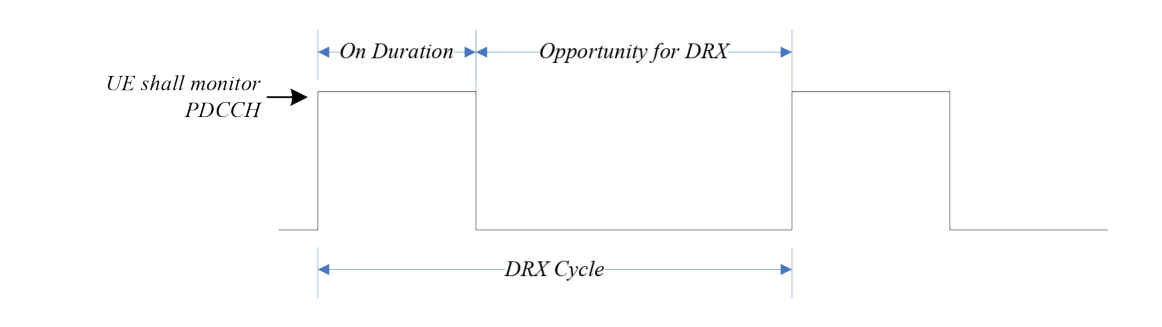
Bandwidth adaptation helps too: with one active bandwidth part, the device watches the control channel only there rather than across the whole cell §11.
Paging in idle and inactive works the same way — the device only has to watch during one paging occasion per cycle §9.2.5.
Which cycle applies is the shortest of those that apply: a default broadcast in system information, a device-specific one from the core, and in inactive a device-specific one from the radio network §9.2.5.
6.8 What the states cost in security terms
Moving from connected to idle deletes things §13.3. The base station and the device throw away the next-hop parameter, the base station key, the four derived keys and the counter that goes with them. The AMF and the device keep the core-network keys.
That is why coming back from idle is expensive and coming back from inactive is not: idle has to rebuild the radio security context from the core keys, and inactive still has one.
Going the other way, on idle-to-connected transitions the radio keys are generated while the core keys are assumed to be there already §13.3.
6.9 Where this meets the rest of the course
The actual message flows in and out of these states — setup, resume, paging, handover — are How a connection is set up, and how it is moved. The keys named here are Where the radio network meets the core.
Which group owns the documents that specify the states in full is The six working groups, and where the line between them runs: the state machine itself is in TS 38.331 and the device-side procedures in TS 38.304, both RAN2's.
Check yourself
Answers appear when you pick one, with where they come from.
Q6.1 In RRC_INACTIVE, who initiates paging?
The state list says paging is initiated by NG-RAN in RRC_INACTIVE, and by the 5GC in RRC_IDLE. A device in RRC_INACTIVE also monitors for core-initiated paging. §7.2
Q6.2 What does the network keep while a device is in RRC_INACTIVE?
In RRC_INACTIVE the last serving gNB keeps the context and the device-associated NG connection with the serving AMF and UPF, so the connection is suspended rather than torn down. §9.2.2.1
Q6.3 What happens to the radio keys when a device goes from connected to idle?
On connected-to-idle transitions the gNB and the device delete NH, KgNB and the four derived keys and the related counter, while AMF and device keep the core keys. §13.3
Q6.4 What is an acceptable cell, as opposed to a suitable one?
A suitable cell also has to belong to the selected, registered or an equivalent network and not be in a forbidden tracking area. An acceptable cell only has to pass the measurement criteria and not be barred. §9.2.1.1
Q6.5 How does a device in RRC_INACTIVE know when to tell the network it has moved?
A notification area update is sent periodically and whenever cell reselection picks a cell that is not in the configured area. §9.2.2.3
Q6.6 Which state is small data transmission designed for?
SDT allows data or signalling to be sent while remaining in RRC_INACTIVE, without transitioning to RRC_CONNECTED. §18.0
This chapter was written against TS 38.300 version 19.3.0, and built from a source register generated 2026-08-04. A newer version of the document may say something else.