The radio itself, as TS 38.300 describes it · chapter 8 of 16 · 9 minutes
8 Where the radio network meets the core
The NG interface, quality of service flows, the identities that cross the boundary, where security terminates, and what the radio network is never told.
Built from §4.2 §4.3.1.1 §4.3.1.2 §7.6 §8.1 §8.2 §8.3 §9.4 §12.1 §13.1 §13.2 §A.1 §A.2
8.1 The boundary is a promise, not a wire
The interesting thing about the NG interface is how little the radio network is told. It is given a handful of parameters per traffic stream and a key, and everything else about the subscriber, the tariff, the policy and the application is kept on the other side.
That is a design choice, and TS 38.300 states it as one: the functional split clause lists what the AMF, the UPF and the SMF host, each time pointing at TS 23.501 for the specification §4.2. This document names them so the picture makes sense and specifies none of them.
8.2 The two planes of NG
NG-U carries the packets: GTP-U over UDP over IP, and non-guaranteed delivery of user plane packets between the NG-RAN node and the UPF §4.3.1.1. Non-guaranteed is the right promise — retransmission is the radio network's job below, and the transport's job above.
NG-C carries the signalling: NGAP over SCTP over IP, where SCTP is what makes delivery guaranteed §4.3.1.2. Its eight functions are interface management, device context management, device mobility management, transport of core-network messages, paging, session management, configuration transfer and warning message transmission.
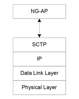
Both clauses point at TS 38.410 for the general principles, and the protocol itself is TS 38.413. Both are RAN3's — see The six working groups, and where the line between them runs.
One small clause is easy to miss and matters when you are debugging transport: the core network may give two transport addresses of different versions so the radio node can pick IPv4 or IPv6 §8.3.
8.3 Quality of service: two mappings, not one
The 5G quality model is built on QoS flows §12.1. A flow either needs a guaranteed bit rate or it does not, and it is identified inside a session by a QoS flow identifier carried in an encapsulation header on NG-U.
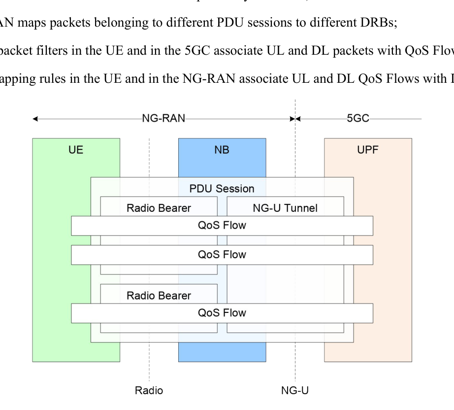
The clause states the granularity plainly:
There are two mappings and they belong to different sides §12.1:
-
Packets to flows is done by the core network and the device, using filters set at the core.
-
Flows to data radio bearers is done by the radio network and the device, using rules the radio network sets.
The radio network gets a QoS profile per flow, and that profile is the whole of what it is told §12.1. For every flow: a 5G QoS identifier and an allocation and retention priority.
For a guaranteed-bit-rate flow also: guaranteed and maximum flow bit rates in both directions, a maximum packet loss rate, a delay-critical resource type and notification control.
The identifier is a pointer, not a number of bits per second. It stands for a set of characteristics — priority level, packet delay budget, packet error rate, averaging window, maximum data burst volume — that are either standardised or pre-configured and therefore never signalled §12.1.
Notification control is the one promise that runs backwards §12.1. If it is switched on for a guaranteed flow and the radio network works out it cannot deliver the guarantee, it must tell the SMF and keep the flow anyway — unless something at the radio side forces a release, such as a radio link failure or congestion. When the guarantee can be met again, it sends another notification.
Three aggregate limits sit on top §12.1: a per-session maximum enforced by the UPF, a per-device maximum enforced by the radio network, and a per-slice per-device maximum also enforced by the radio network.
8.4 How the uplink mapping is taught to the device
Uplink flow-to-bearer mapping reaches the device in one of two ways §12.1.
Reflective mapping: the device watches the flow identifiers on downlink packets for a bearer and applies the same mapping upwards. For this to work the radio network marks the downlink packets with the identifier over the radio interface.
Explicit configuration: RRC signals the rules.
The device always applies the latest rule, whichever way it arrived, and sends an end marker on the old bearer when a rule changes §12.1.
Each session may also have a default bearer: an uplink packet that matches neither a configured nor a reflective rule goes there §12.1.
The annex works the two cases through as message flows.
Session establishment §A.1 runs from the device's request through a resource setup request from the AMF, a reconfiguration that sets up at least one bearer, and a response back.
A note at the end of that flow settles a question people ask often: flow-identifier marking over the radio interface is optional, while marking over NG-U is always present §A.1.
The reflective case §A.2 is shorter: a downlink packet arrives with a flow identifier that has no bearer association yet, the base station picks an existing bearer, sends the packet with the identifier and a reflective indication set, and the device updates its own rules from what it saw.
8.5 The identities that cross
The radio network keeps two families of identity apart §8.1 §8.2.
Device identities are radio identities and mostly temporary: the C-RNTI for scheduling, the temporary C-RNTI during random access, the P-RNTI for paging, the SI-RNTI for broadcast and the I-RNTI for a suspended context.
The same clause lists many more, for power control, slot format, semi-persistent scheduling, power saving and multicast §8.1.
Network identities are structural §8.2:
| Identity | Built from |
|---|---|
| NCGI, the global cell identity | network identity + NR cell identity |
| gNB ID | contained inside the NR cell identity |
| Global gNB ID | network identity + gNB ID |
| TAI, the tracking area identity | network identity + tracking area code |
| S-NSSAI | identifies one network slice |
| NID | identifies a stand-alone non-public network with a network identity |
The pattern is worth noticing: every global identity is a local one with a network identity glued in front. That is what makes a cell identity meaningful across an interface between two operators.
8.6 Where security stops
The termination table is three rows and settles most arguments §13.2:
| Ciphering | Integrity protection | |
|---|---|---|
| Core-network signalling | AMF | AMF |
| RRC signalling | gNB | gNB |
| User plane data | gNB | gNB |
The principles behind it are stated in the clause above §13.1. The radio keys are cryptographically separated from the core keys. There are separate security mode command procedures for the two levels.
A counter is used as input to ciphering and integrity protection, and a given counter value must be used only once for a given key on a given bearer in a given direction.
Integrity protection is always configured for RRC signalling; everything else is optional per bearer, except where the core network's user-plane security enforcement says integrity is required, and then every bearer of that session gets it §13.1.
The key chain runs downwards from an anchor key established at authentication: the AMF key from the anchor, the core signalling keys and the base station key from the AMF key, and the four radio keys from the base station key §13.1.
Handovers derive a new base station key from either the current one — a horizontal derivation, signalled by a counter that does not increase — or from a next-hop parameter — a vertical derivation, signalled by a counter that does §13.1.
The consequence is stated in the clause: a base station knowing the current key cannot compute a previous one, and cannot predict a future one after enough handovers.
8.7 What the radio network is told about roaming
The AMF may send roaming and access restriction information §9.4: forbidden radio technologies, forbidden areas, service area restrictions, the serving network, a list of equivalent networks and possibly non-public network restrictions.
The base station uses it to decide whether to restrict a later handover or redirection. Where it has none, it treats the device as unrestricted — with the non-public network case called out as the exception §9.4.
The clause then does something unusual and admits an interoperability problem: where nodes run different protocol versions, the restriction list can be lost across an Xn handover, so the source may pass the core network's original list along in a container that the target uses as-is §9.4.
8.8 What the radio network never reads
Core-network messages travel through the radio network in transparent containers §7.6. RRC gives them reliable in-sequence delivery over the signalling bearers, with the caveat that losses or duplication can happen at handover when PDCP is re-established.
They can be piggybacked: on bearer establishment, modification or release in the downlink, and on the first message during connection setup and resume in the uplink §7.6.
Several can travel in one downlink RRC message, and then their order must match the order in the corresponding NG message so in-sequence delivery survives.
8.9 Where this meets the rest of the course
The bearers the flows are mapped onto are The radio protocol stack, sublayer by sublayer. The path switch that moves a session's downlink to a new base station is How a connection is set up, and how it is moved.
Which group writes each side of this boundary — and what actually crosses between the radio groups and the core-network groups in practice — is Where RAN meets the groups that write the rest of 3GPP.
Check yourself
Answers appear when you pick one, with where they come from.
Q8.1 What is the finest granularity of quality-of-service differentiation in a PDU session?
The QoS clause says the QoS flow is the finest granularity at NAS level, identified inside a session by a QoS flow identifier carried in an encapsulation header over NG-U. §12.1
Q8.2 Where is user plane data ciphered?
The security termination table gives the AMF for core-network signalling and the gNB for both RRC signalling and user plane data, ciphering and integrity alike. §13.2
Q8.3 What is reflective mapping?
For each bearer the device watches the flow identifiers of downlink packets and applies the same mapping upwards. The other way is explicit configuration by RRC. §12.1
Q8.4 What does the radio network do with a core-network message it carries?
NAS messages are sent in transparent containers in RRC, with reliable in-sequence delivery over signalling radio bearers. §7.6
Q8.5 What is an NCGI built from?
The NR Cell Global Identifier is constructed from the network identity the cell belongs to and the NR Cell Identity of the cell, and the gNB identity is contained within that cell identity. §8.2
Q8.6 What happens if a base station has no roaming and access restriction information for a device?
The clause says the gNB shall consider there is no restriction for subsequent mobility actions, with the PNI-NPN case called out as the exception. §9.4
This chapter was written against TS 38.300 version 19.3.0, and built from a source register generated 2026-08-04. A newer version of the document may say something else.