3GPP 38.300 v19.3.0 — the document's own text
9.2.1.3 State Transitions
Taught in 7. How a connection is set up, and how it is moved (TSG RAN — the group that specifies the radio, in depth), 5. The layers a packet falls through, and the three states a device sits in (TSG RAN — the group that specifies the radio, overview).
The following figure describes the UE triggered transition from RRC_IDLE to RRC_CONNECTED (for the NAS part, see TS 23.502 [22]):
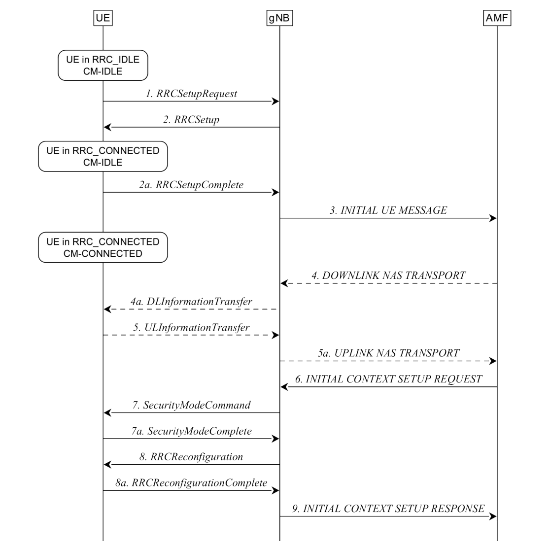
1. The UE requests to setup a new connection from RRC_IDLE.
2/2a. The gNB completes the RRC setup procedure.
NOTE 0: The scenario where the gNB rejects the request is described below.
3. The first NAS message from the UE, piggybacked in RRCSetupComplete, is sent to AMF.
4/4a/5/5a. Additional NAS messages may be exchanged between UE and AMF, see TS 23.502 [22].
6. The AMF prepares the UE context data (including PDU session context, the Security Key, UE Radio Capability and UE Security Capabilities, etc.) and sends it to the gNB.
7/7a. The gNB activates the AS security with the UE.
8/8a. The gNB performs the reconfiguration to setup SRB2 and DRBs for UE, or SRB2 and optionally DRBs for IAB-MT.
9. The gNB informs the AMF that the setup procedure is completed.
NOTE 1: RRC messages in step 1 and 2 use SRB0, all the subsequent messages use SRB1. Messages in steps 7/7a are integrity protected. From step 8 on, all the messages are integrity protected and ciphered.
NOTE 2: For signalling only connection, step 8 is skipped since SRB2 and DRBs are not setup.
The following figure describes the rejection from the network when the UE attempts to setup a connection from RRC_IDLE:
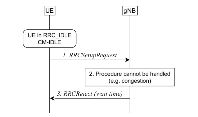
1. UE attempts to setup a new connection from RRC_IDLE.
2. The gNB is not able to handle the procedure, for instance due to congestion.
3. The gNB sends RRCReject (with a wait time) to keep the UE in RRC_IDLE.