3GPP 38.300 v19.3.0 — the document's own text
9.2.3.2.1 C-Plane Handling
Taught in 7. How a connection is set up, and how it is moved (TSG RAN — the group that specifies the radio, in depth).
The intra-NR RAN handover performs the preparation and execution phase of the handover procedure performed without involvement of the 5GC, i.e. preparation messages are directly exchanged between the gNBs. The release of the resources at the source gNB during the handover completion phase is triggered by the target gNB. The figure below depicts the basic handover scenario where neither the AMF nor the UPF changes:
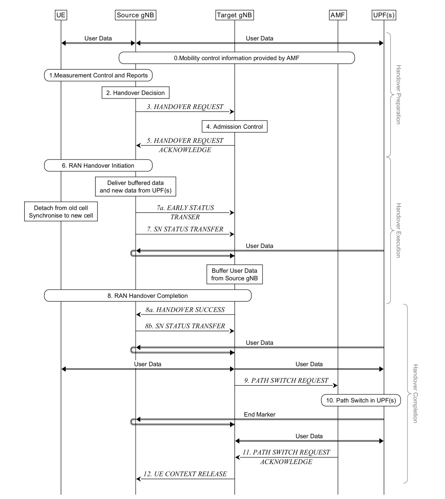
0. The UE context within the source gNB contains information regarding roaming and access restrictions which were provided either at connection establishment or at the last TA update.
1. The source gNB configures the UE measurement procedures and the UE reports according to the measurement configuration.
2. The source gNB decides to handover the UE, based on MeasurementReport and RRM information.
3. The source gNB issues a Handover Request message to the target gNB passing a transparent RRC container with necessary information to prepare the handover at the target side. The information includes at least the target cell ID, KgNB*, the C-RNTI of the UE in the source gNB, RRM-configuration including UE inactive time, basic AS-configuration including antenna Info and DL Carrier Frequency, the current QoS flow to DRB mapping rules applied to the UE, the SIB1 information from source gNB, the UE capabilities for different RATs, PDU session related information, and can include the UE reported measurement information including beam-related information if available. The PDU session related information includes the slice information and QoS flow level QoS profile(s). The source gNB may also request a DAPS handover for one or more DRBs.
NOTE 1: After issuing a Handover Request, the source gNB should not reconfigure the UE, including performing Reflective QoS flow to DRB mapping.
4. Admission Control may be performed by the target gNB. Slice-aware admission control shall be performed if the slice information is sent to the target gNB. If the PDU sessions are associated with non-supported slices the target gNB shall reject such PDU Sessions.
5. The target gNB prepares the handover with L1/L2 and sends the HANDOVER REQUEST ACKNOWLEDGE to the source gNB, which includes a transparent container to be sent to the UE as an RRC message to perform the handover. The target gNB also indicates if a DAPS handover is accepted.
NOTE 2: As soon as the source gNB receives the HANDOVER REQUEST ACKNOWLEDGE, or as soon as the transmission of the handover command is initiated in the downlink, data forwarding may be initiated.
NOTE 3: For DRBs configured with DAPS, downlink PDCP SDUs are forwarded with SN assigned by the source gNB, until SN assignment is handed over to the target gNB in step 8b, for which the normal data forwarding follows as defined in 9.2.3.2.3.
6. The source gNB triggers the Uu handover by sending an RRCReconfiguration message to the UE, containing the information required to access the target cell: at least the target cell ID, the new C-RNTI, the target gNB security algorithm identifiers for the selected security algorithms. It can also include a set of dedicated RACH resources, the association between RACH resources and SSB(s), the association between RACH resources and UE-specific CSI-RS configuration(s), common RACH resources, and system information of the target cell, etc.
NOTE 4: For DRBs configured with DAPS, the source gNB does not stop transmitting downlink packets until it receives the HANDOVER SUCCESS message from the target gNB in step 8a.
NOTE 4a: CHO cannot be configured simultaneously with DAPS handover.
7a. For DRBs configured with DAPS, the source gNB sends the EARLY STATUS TRANSFER message. The DL COUNT value conveyed in the EARLY STATUS TRANSFER message indicates PDCP SN and HFN of the first PDCP SDU that the source gNB forwards to the target gNB. The source gNB does not stop assigning SNs to downlink PDCP SDUs until it sends the SN STATUS TRANSFER message to the target gNB in step 8b.
7. For DRBs not configured with DAPS, the source gNB sends the SN STATUS TRANSFER message to the target gNB to convey the uplink PDCP SN receiver status and the downlink PDCP SN transmitter status of DRBs for which PDCP status preservation applies (i.e. for RLC AM). The uplink PDCP SN receiver status includes at least the PDCP SN of the first missing UL PDCP SDU and may include a bit map of the receive status of the out of sequence UL PDCP SDUs that the UE needs to retransmit in the target cell, if any. The downlink PDCP SN transmitter status indicates the next PDCP SN that the target gNB shall assign to new PDCP SDUs, not having a PDCP SN yet.
NOTE 5: In case of DAPS handover, the uplink PDCP SN receiver status and the downlink PDCP SN transmitter status for a DRB with RLC-AM and not configured with DAPS may be transferred by the SN STATUS TRANSFER message in step 8b instead of step 7.
NOTE 6: For DRBs configured with DAPS, the source gNB may additionally send the EARLY STATUS TRANSFER message(s) between step 7 and step 8b, to inform discarding of already forwarded PDCP SDUs. The target gNB does not transmit forwarded downlink PDCP SDUs to the UE, whose COUNT is less than the conveyed DL COUNT value and discards them if transmission has not been attempted already.
8. The UE synchronises to the target cell and completes the RRC handover procedure by sending RRCReconfigurationComplete message to target gNB. In case of DAPS handover, the UE does not detach from the source cell upon receiving the RRCReconfiguration message. The UE releases the source resources and configurations and stops DL/UL reception/transmission with the source upon receiving an explicit release from the target node.
NOTE 6a: From RAN point of view, the DAPS handover is considered to only be completed after the UE has released the source cell as explicitly requested from the target node. RRC suspend, a subsequent handover or inter-RAT handover cannot be initiated until the source cell has been released.
8a/b In case of DAPS handover, the target gNB sends the HANDOVER SUCCESS message to the source gNB to inform that the UE has successfully accessed the target cell. In return, the source gNB sends the SN STATUS TRANSFER message for DRBs configured with DAPS for which the description in step 7 applies, and the normal data forwarding follows as defined in 9.2.3.2.3.
NOTE 7: The uplink PDCP SN receiver status and the downlink PDCP SN transmitter status are also conveyed for DRBs with RLC-UM in the SN STATUS TRANSFER message in step 8b, if configured with DAPS.
NOTE 8: For DRBs configured with DAPS, the source gNB does not stop delivering uplink QoS flows to the UPF until it sends the SN STATUS TRANSFER message in step 8b. The target gNB does not forward QoS flows of the uplink PDCP SDUs successfully received in-sequence to the UPF until it receives the SN STATUS TRANSFER message, in which UL HFN and the first missing SN in the uplink PDCP SN receiver status indicates the start of uplink PDCP SDUs to be delivered to the UPF. The target gNB does not deliver any uplink PDCP SDUs which has an UL COUNT lower than the provided.
NOTE 9: Void.
9. The target gNB sends a PATH SWITCH REQUEST message to AMF to trigger 5GC to switch the DL data path towards the target gNB and to establish an NG-C interface instance towards the target gNB.
10. 5GC switches the DL data path towards the target gNB. The UPF sends one or more "end marker" packets on the old path to the source gNB per PDU session/tunnel and then can release any U-plane/TNL resources towards the source gNB.
11. The AMF confirms the PATH SWITCH REQUEST message with the PATH SWITCH REQUEST ACKNOWLEDGE message.
12. Upon reception of the PATH SWITCH REQUEST ACKNOWLEDGE message from the AMF, the target gNB sends the UE CONTEXT RELEASE to inform the source gNB about the success of the handover. The source gNB can then release radio and C-plane related resources associated to the UE context. Any ongoing data forwarding may continue.
The RRM configuration can include both beam measurement information (for layer 3 mobility) associated to SSB(s) and CSI-RS(s) for the reported cell(s) if both types of measurements are available. Also, if CA is configured, the RRM configuration can include the list of best cells on each frequency for which measurement information is available. And the RRM measurement information can also include the beam measurement for the listed cells that belong to the target gNB.
The common RACH configuration for beams in the target cell is only associated to the SSB(s). The network can have dedicated RACH configurations associated to the SSB(s) and/or have dedicated RACH configurations associated to CSI-RS(s) within a cell. The target gNB can only include one of the following RACH configurations in the Handover Command to enable the UE to access the target cell:
- Common RACH configuration;
- Common RACH configuration + Dedicated RACH configuration associated with SSB;
iii) Common RACH configuration + Dedicated RACH configuration associated with CSI-RS.
The dedicated RACH configuration allocates RACH resource(s) together with a quality threshold to use them. When dedicated RACH resources are provided, they are prioritized by the UE and the UE shall not switch to contention-based RACH resources as long as the quality threshold of those dedicated resources is met. The order to access the dedicated RACH resources is up to UE implementation.
Upon receiving a handover command requesting DAPS handover, the UE suspends source cell SRBs, stops sending and receiving any RRC control plane signalling toward the source cell, and establishes SRBs for the target cell. The UE releases the source cell SRBs configuration upon receiving source cell release indication from the target cell after successful DAPS handover execution. When DAPS handover to the target cell fails and if the source cell link is available, then the UE reverts back to the source cell configuration and resumes source cell SRBs for control plane signalling transmission.