3GPP 38.300 v19.3.0 — the document's own text
6.1 Overview
Taught in 2. The six working groups, and where the line between them runs (TSG RAN — the group that specifies the radio, in depth), 5. The radio protocol stack, sublayer by sublayer (TSG RAN — the group that specifies the radio, in depth), 2. The six working groups and the line between them (TSG RAN — the group that specifies the radio, overview), 5. The layers a packet falls through, and the three states a device sits in (TSG RAN — the group that specifies the radio, overview), 3. What NR is, read off the document itself (TSG RAN — the group that specifies the radio, quick start).
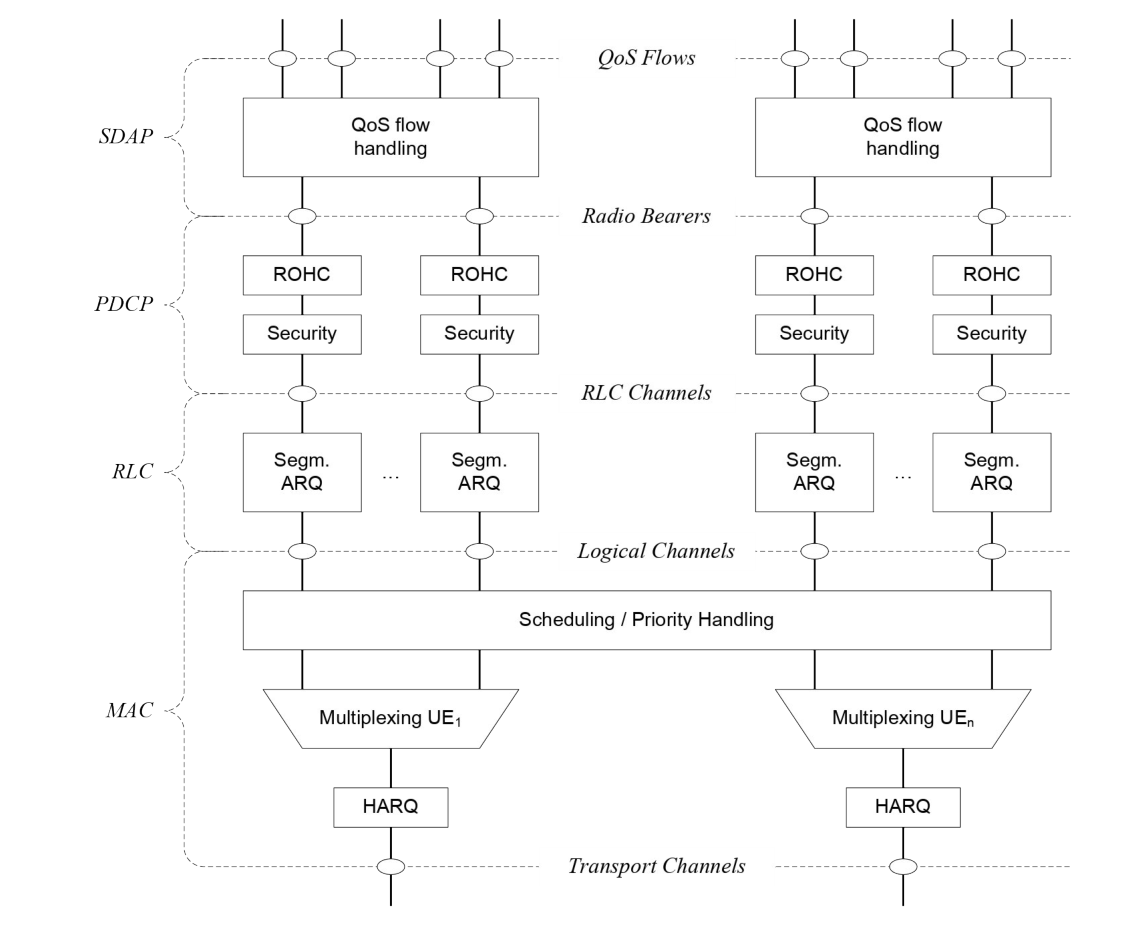
The layer 2 of NR is split into the following sublayers: Medium Access Control (MAC), Radio Link Control (RLC), Packet Data Convergence Protocol (PDCP) and Service Data Adaptation Protocol (SDAP). The two figures below depict the Layer 2 architecture for downlink and uplink, where:
- The physical layer offers to the MAC sublayer transport channels;
- The MAC sublayer offers to the RLC sublayer logical channels;
- The RLC sublayer offers to the PDCP sublayer RLC channels;
- The PDCP sublayer offers to the SDAP sublayer radio bearers;
- The SDAP sublayer offers to 5GC QoS flows;
- Comp. refers to header compression or uplink data compression;
- Segm. refers to segmentation;
- Control channels (BCCH, PCCH are not depicted for clarity).
NOTE: The gNB may not be able to guarantee that a L2 buffer overflow will never occur. If such overflow occurs, the UE may discard packets in the L2 buffer.
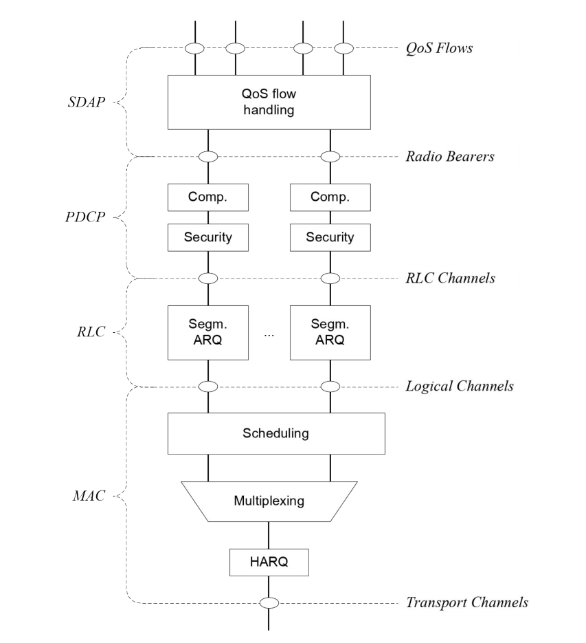
Radio bearers are categorized into two groups: data radio bearers (DRB) for user plane data and signalling radio bearers (SRB) for control plane data.
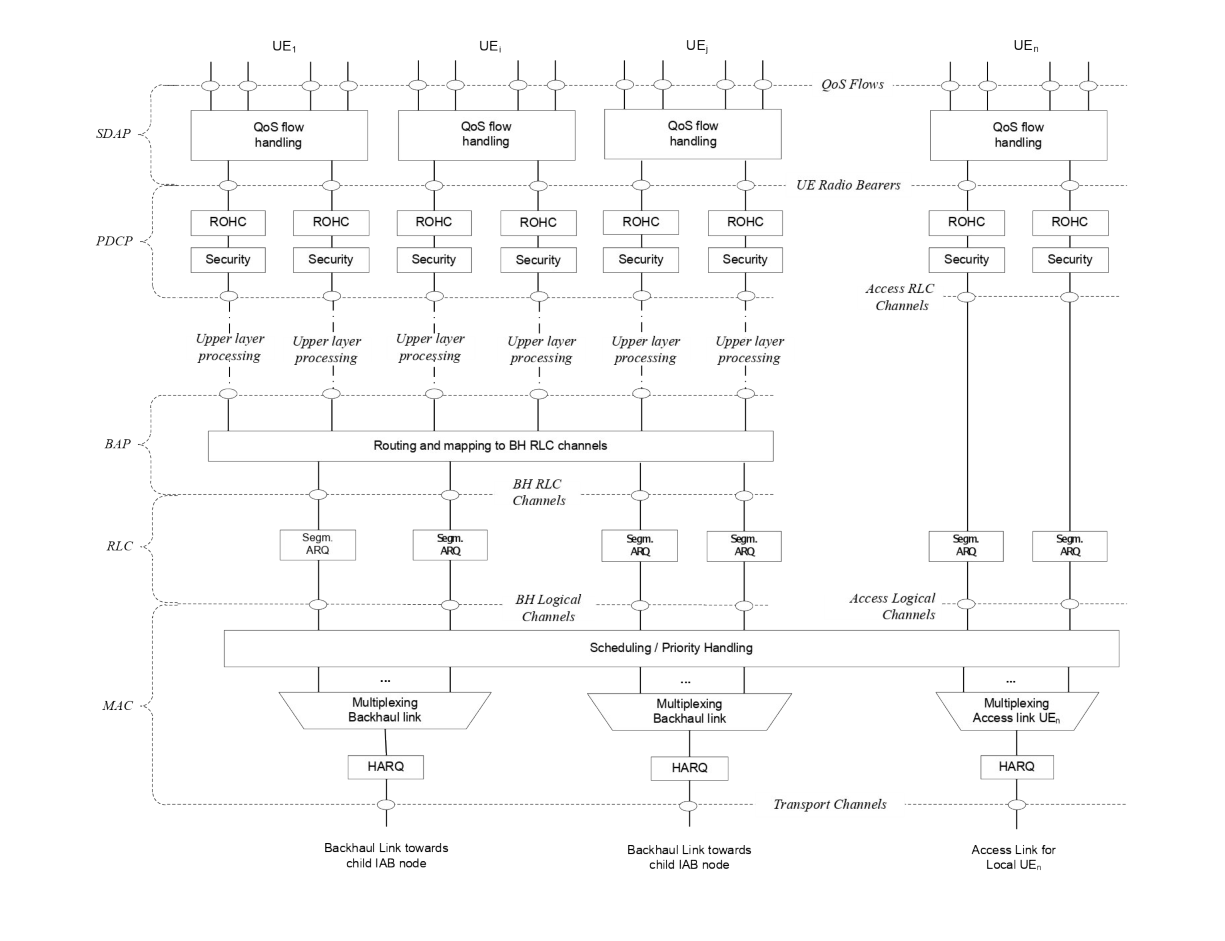
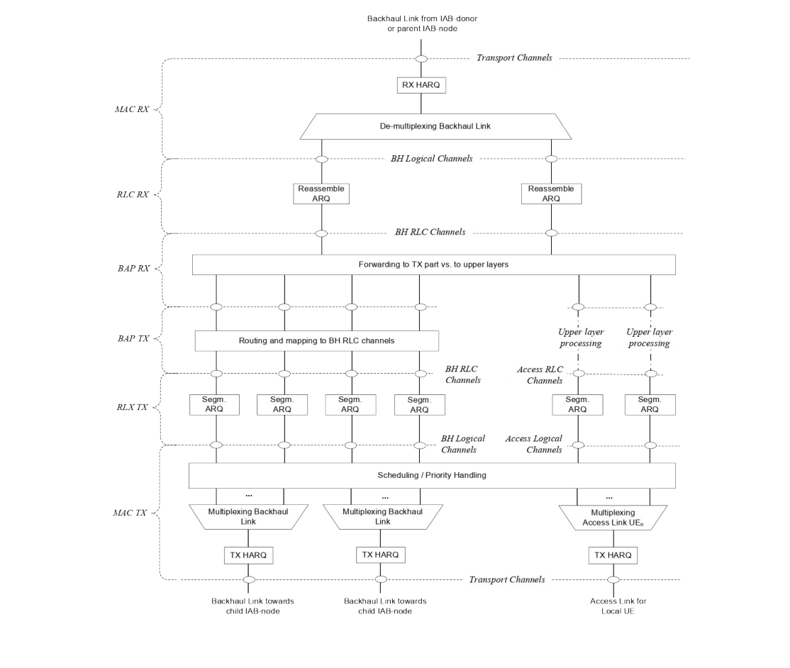
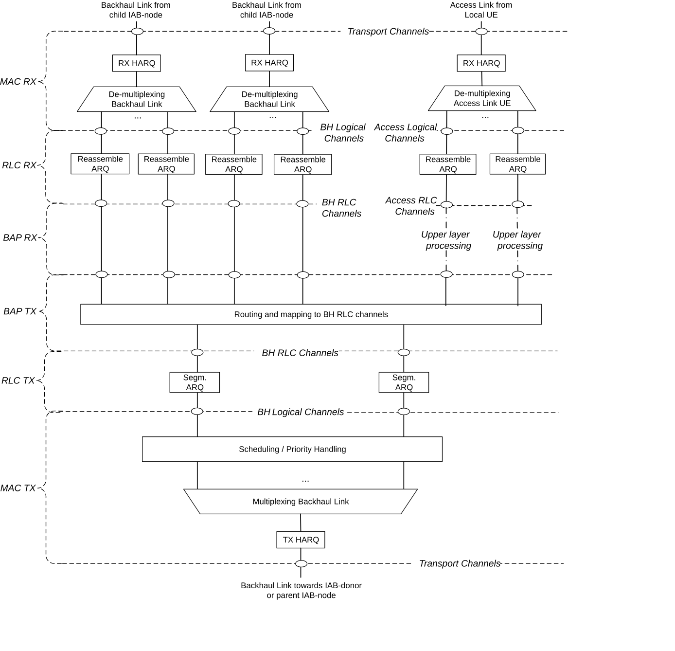
For IAB, the Layer 2 of NR includes: MAC, RLC, Backhaul Adaptation Protocol (BAP), PDCP and optionally SDAP. The BAP sublayer supports routing across the IAB topology and traffic mapping to BH RLC channels for enforcement of traffic prioritization and QoS.
Figures 6.1-3 below depicts the Layer-2 architecture for downlink on the IAB-donor. Figures 6.1-4 and 6.1-5 depict the Layer-2 architecture for downlink and uplink on the IAB-node, where the BAP sublayer offers routing functionality and mapping to BH RLC channels.