What the radio actually is · chapter 4 of 7 · 6 minutes
4 What NR actually is, in the shape its own document gives it
The two kinds of base station, the three interfaces, what a base station is responsible for, and the shape of the signal — read off TS 38.300 rather than described from outside.
Built from §1 §4.1 §4.2 §4.3 §4.5 §4.6 §4.7 §4.8 §4.9 §4.10 §4.11 §5.1 §5.5 §6.10 §12.1 §14
4.1 What the document is for
TS 38.300 is the map of the 5G radio. NR is the radio itself, and NG-RAN is the network of base stations that speaks it.
The document says what it covers in its first sentence, and it is worth taking literally: it is an overview, and the working detail lives elsewhere §1.
That matters when somebody quotes it in an argument. It settles what the parts are and who is responsible for what. It does not settle a single bit on the air.
4.2 Two kinds of base station
An NG-RAN node is one of two things. A gNB gives the device NR user plane and control plane terminations. An ng-eNB gives it the 4G radio's terminations instead, while still hanging off a 5G core §4.1.
Both are joined to each other the same way, and to the core the same way:
The AMF is the function that tracks where a device is and whether it can be reached; the UPF is the one that actually forwards the user's packets.
A base station can also be split into parts internally. TS 38.300 does not describe that split — it points at TS 38.401, which belongs to RAN3 §4.1 TS 38.401.
4.3 Three interfaces, two halves each
Each interface has a user-plane half for the traffic and a control-plane half for the signalling, and the two are built differently.
-
NG-U, between a base station and the UPF, carries user packets in GTP-U over UDP/IP and gives non-guaranteed delivery §4.3.1.1.
-
NG-C, between a base station and the AMF, adds SCTP on top of IP so that signalling arrives reliably, and runs the NGAP protocol over it. Its jobs include interface management, UE context management, mobility, transport of NAS messages, paging and PDU session management §4.3.1.2.
-
Xn-U, between two base stations, is GTP-U again, and does two things: forwarding data and flow control §4.3.2.1.
-
Xn-C, between two base stations, runs XnAP over SCTP and handles interface management, mobility including context transfer and RAN paging, and dual connectivity §4.3.2.2.
4.4 What the base station is answerable for
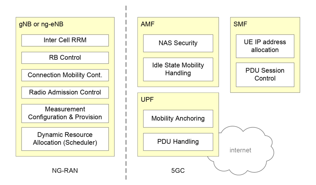
Clause 4.2 is a long list, and reading it is the fastest way to see where the radio side stops and the core begins §4.2.
The base station holds radio resource management — radio bearer control, radio admission control, connection mobility control, and the dynamic allocation of resources to devices, which is scheduling.
It also does header compression, encryption and integrity protection of data, connection setup and release, the scheduling and transmission of paging and of system broadcast information, measurement configuration, QoS flow management and mapping to data radio bearers, network slicing support, radio access network sharing and dual connectivity.
The core keeps the things that are not about radio: the AMF terminates the signalling to the device that is not radio-specific, handles registration areas and mobility, and selects a session function; the UPF is the anchor and the forwarder §4.2.
4.5 The shape of the signal
Clause 5.1 gives the air interface in one page §5.1.
The downlink waveform is conventional OFDM with a cyclic prefix. The uplink is the same, with an extra transform step that can be switched on or off.
Subcarrier spacing is not one number but a ladder: 2 to the power µ, times 15 kHz. Twelve consecutive subcarriers make a physical resource block, and a carrier holds up to 275 of them.
Time is regular. Frames are 10 ms, made of ten 1 ms subframes, split into two half-frames of five. A slot is 14 symbols with the normal cyclic prefix, and it shrinks as the subcarrier spacing grows, so a subframe always holds a whole number of slots.
A device is given one or more bandwidth parts on a carrier, and only one of them is active at a time §5.1. The width can be ordered to change — to shrink during a quiet period and save power, for instance §6.10.
Below all of that sit the transport channels the physical layer offers upwards: BCH, DL-SCH and PCH going down, UL-SCH and RACH coming up §5.5.
4.6 Two more shapes worth knowing
Two schedulers at once. A connected device can be told to use radio from two different NG-RAN nodes with two separate schedulers, joined by an ordinary backhaul link — one giving NR, the other NR or the 4G radio §4.5.
One mast, several operators. A shared cell broadcasts a tracking area code and a cell identity for each subset of networks that shares it §4.6.
4.7 Masts that are not ordinary masts
The same clause 4 also names the shapes that are not one box on one tower, and knowing they exist saves a lot of confused reading later.
-
Wireless relaying, called integrated access and backhaul. A relay node serves devices over NR and reaches the network over NR as well, through one hop or several, with a donor base station at the root of the tree §4.7.
-
A controlled repeater: a radio amplifier that forwards signals on, with a small device-like part that listens to the base station for side control information telling it how to behave §4.9.
-
Wireless access backhaul: a node that is a base station towards devices and a device towards another base station, and which may be stationary or moving §4.11.
-
Small nodes, called NR Femto nodes, which may reach the core directly or through a gateway that looks like a base station to the core and like the core to them §4.10.
-
Networks that are not public at all, either standing alone or leaning on a public operator's network §4.8.
4.8 What the network promises
The unit of quality is the QoS flow, and it is marked with a QoS flow ID carried in a header on the interface to the core §12.1.
Capabilities work the same way — by structure rather than by product tier. NR has no device categories with fixed peak rates; a device reports what it can do per band and per band combination §14.
The next chapter, The layers a packet falls through, and the three states a device sits in, goes one level in: the layers that make this work and the three states a device sits in.
Check yourself
Answers appear when you pick one, with where they come from.
Q4.1 What are the two kinds of node an NG-RAN can be built from?
A gNB gives the device NR user plane and control plane terminations; an ng-eNB gives it E-UTRA terminations. Both are NG-RAN nodes. §4.1
Q4.2 Which interface joins two base stations to each other?
The gNBs and ng-eNBs are interconnected by the Xn interface, and connected to the core by the NG interfaces. §4.1
Q4.3 What is the difference between the user-plane and control-plane halves of the NG interface?
NG-U uses GTP-U over UDP/IP and provides non-guaranteed delivery. NG-C adds SCTP for reliable transport and carries NGAP. §4.3.1.2
Q4.4 How is the subcarrier spacing of NR defined?
The numerology scales exponentially, and twelve consecutive subcarriers make one physical resource block. §5.1
Q4.5 How long is a radio frame, and what is it made of?
Frames are 10 ms and hold ten 1 ms subframes, split into two equal half-frames of five subframes each. §5.1
Q4.6 Does NR use UE categories with fixed peak data rates?
Capabilities are reported per band and per band combination instead. The document says categories exist for marketing purposes and are not signalled. §14
This chapter was written against TS 38.300 version 19.3.0, and built from a source register generated 2026-08-04. A newer version of the document may say something else.