What the radio actually is · chapter 5 of 7 · 6 minutes
5 The layers a packet falls through, and the three states a device sits in
The user-plane and control-plane stacks, what each of the four layer-2 sublayers does, what RRC is for, and the difference between idle, inactive and connected.
Built from §4.4 §6.1 §6.2 §6.3 §6.4 §6.5 §6.6 §6.10 §7.1 §7.2 §8.1 §9.2.1.3 §9.2.2.1 §10.1 §11 §13.2
5.1 Two stacks, not one
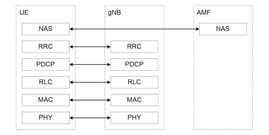
Traffic and control travel over the same radio but through different piles of software, and the document draws them separately.
On the user plane, four sublayers sit between the application's packets and the physical layer: SDAP, PDCP, RLC and MAC. On the network side, all four end in the base station §4.4.
On the control plane, three of them are the same — PDCP, RLC and MAC — with RRC above them, also ending in the base station. Above RRC sits NAS, the signalling between the device and the core, and that one runs past the base station and ends at the AMF §4.4.
5.2 The stack as a chain of offers
Clause 6.1 describes the layers not by what they contain but by what each one offers upwards, which is the more useful way round §6.1:
- the physical layer offers the MAC sublayer transport channels;
- MAC offers RLC logical channels;
- RLC offers PDCP RLC channels;
- PDCP offers SDAP radio bearers;
- SDAP offers the core QoS flows.
Radio bearers come in two kinds: data radio bearers for user traffic and signalling radio bearers for control §6.1.
5.3 What each sublayer actually does
MAC is the scheduler's end of the deal. It maps logical channels onto transport channels, multiplexes several channels into one transport block, reports scheduling information, runs HARQ for error correction, and handles priority — between devices by scheduling, and between one device's own channels by logical channel prioritisation §6.2.
RLC has three modes: transparent, unacknowledged and acknowledged. Only acknowledged mode does ARQ, retransmitting on the strength of status reports. Segmentation, reassembly and discard live here too §6.3.
The mode is chosen by what is carried: transparent mode for the first signalling bearer, paging and broadcast system information; acknowledged mode for the other signalling bearers; either unacknowledged or acknowledged for data §6.3.
PDCP is where the packet becomes safe and orderly. It compresses headers, ciphers, integrity-protects, discards on a timer, reorders, and can duplicate a packet across two paths §6.4.
SDAP is the thinnest and the newest: it maps a QoS flow to a data radio bearer and marks the QoS flow ID in packets going each way. One SDAP entity exists per PDU session §6.5.
An example of all four working on one transport block is drawn in the document itself §6.6.
5.4 The channels underneath
Logical channels are named by what they carry, not by where they go §6.2:
| Channel | What travels on it |
|---|---|
| BCCH | broadcast system control information |
| PCCH | paging messages |
| CCCH | control for a device with no connection yet |
| DCCH | control for a device that has one |
| DTCH | one device's user traffic |
5.5 RRC, the conversation about the connection
RRC is the protocol that sets up, changes and tears down the radio connection.
Its list of jobs reads like a summary of the whole radio side: broadcasting system information, paging, establishing and releasing the connection, key management, setting up bearers, handover and cell reselection, configuring measurements, recovering from radio link failure, and carrying NAS messages through §7.1.
Security has two termination points and they are not the same. NAS signalling is ciphered and integrity-protected at the AMF; RRC signalling and user plane data at the base station §13.2.
5.6 Three states
RRC supports three states, and the document characterises each by what the network and the device still hold §7.2.
RRC_IDLE — the device chooses a network, reads broadcast information, moves by reselecting cells on its own, and is paged by the core.
RRC_CONNECTED — there is a connection to the core in both planes, the context is held in the network, the network knows which cell the device is in, and mobility is network-controlled with measurements.
RRC_INACTIVE — the middle state, and the interesting one:
The identifiers differ with the state too. A cell-level identifier, the C-RNTI, names the connection and is used for scheduling; a separate one, the I-RNTI, identifies the stored context in RRC_INACTIVE §8.1.
5.7 Who decides what is sent, and when
Under all of it sits the scheduler, which lives in MAC in the base station and hands out physical resources in both directions §10.1.
It works from two things: what each device has waiting, and what the radio between them will bear. Both are reported upwards. A buffer status report says how much data is queued in the device; a power headroom report says how much transmit power it has left over §10.1.
That is the loop the whole radio runs in: report, decide, grant, transmit.
5.8 Doing nothing, cheaply
A connected device does not have to watch the control channel all the time, and the document has a whole clause on not watching it §11.
The mechanism is a cycle with an on-duration during which the device watches for a grant, plus an inactivity timer that keeps it awake while something is happening and lets it sleep again when nothing is §11.
Bandwidth helps too. With only one bandwidth part active, the device watches for control on that part rather than across the whole carrier, and an inactivity timer of its own drops it back to the default part §6.10 §11.
5.9 From nothing to connected
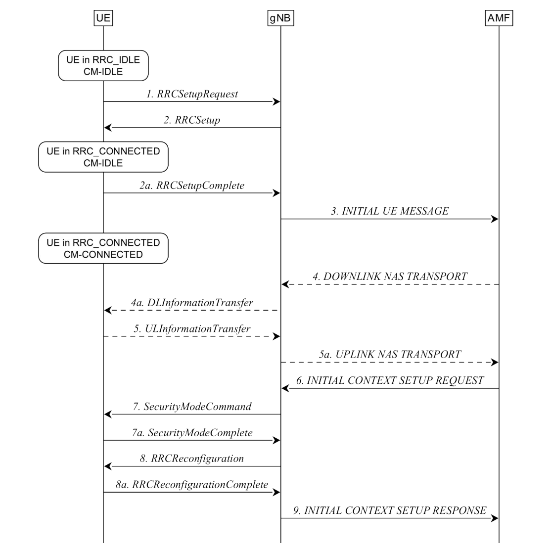
The document draws the transition from idle to connected as a numbered exchange: the device asks for a connection, the base station completes the setup, the first NAS message is passed up to the AMF, the AMF sends down the device's context, security is switched on, and only then are the second signalling bearer and the data bearers configured §9.2.1.3.
The order matters: the reconfiguration that adds data bearers happens after security is running, not before.
The network may also simply say no. A base station that cannot take the request sends a rejection carrying a wait time, and the device stays where it was §9.2.1.3.
With the shape and the layers in hand, How a radio feature travels from a question to a rule turns to how any of this gets written in the first place.
Check yourself
Answers appear when you pick one, with where they come from.
Q5.1 Which four sublayers is layer 2 of NR split into?
RRC is layer 3 and the physical layer is layer 1. Layer 2 is exactly those four sublayers. §6.1
Q5.2 Which sublayer maps a QoS flow onto a data radio bearer?
SDAP does the mapping and marks the QoS flow ID in both directions. One SDAP entity is configured per PDU session. §6.5
Q5.3 In which RLC mode is ARQ — retransmission based on status reports — available?
RLC has Transparent, Unacknowledged and Acknowledged modes. Error correction through ARQ is listed for Acknowledged Mode only. §6.3
Q5.4 In RRC_INACTIVE, where is the device's context kept?
The last serving base station keeps the context and the connection to the core, which is what makes resuming cheap. §9.2.2.1
Q5.5 A device moves inside its RAN-based notification area while in RRC_INACTIVE. What must it do?
The whole point of the area is that movement inside it needs no signalling. Leaving it triggers an update. §9.2.2.1
Q5.6 Where is RRC signalling ciphered and integrity-protected?
The termination table puts NAS signalling at the AMF, and both RRC signalling and user plane data at the gNB. §13.2
This chapter was written against TS 38.300 version 19.3.0, and built from a source register generated 2026-08-04. A newer version of the document may say something else.