The system in one piece · chapter 8 of 27 · 10 minutes
8 What actually travels on the wire
The layers that carry 5G signalling and user data — NGAP over SCTP on N2, NAS on N1, GTP-U over UDP and IP on N3 and N9 — and what each hop adds.
Built from §8
8.1 Why the document needs a clause about layers
Everywhere else, TS 23.501 draws boxes joined by lines with names like N1, N2, N3, N4 and N9. A line is not a protocol. Clause 8 is where the document says what actually runs on each of them, between the device and the core, between the access network and the core, and between core functions §8.1.
It is a short clause, and a lot of it is a pointer rather than a picture: three stacks are named only by the specification that defines them. Know that before you read it. The gaps are real, and the temptation to fill them from memory of some other system is exactly the mistake this chapter is here to prevent.
The boxes and the reference points themselves are The shape of the 5G core and What each network function does.
8.2 N2: one signalling protocol, whatever the access is
N2 runs between an access node and the AMF (the function that tracks where a device is and whether it can be reached). Its stack is four layers under one application protocol.
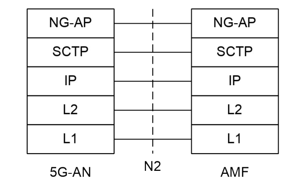
NGAP, the NG Application Protocol, is the application-layer protocol between the access node and the AMF, defined in TS 38.413. Under it, SCTP guarantees delivery of signalling messages between the two, defined in RFC 4960.
Under that, ordinary IP and whatever link and physical layers the transport network happens to have §8.2.1.2. A note adds that N2 maps to NG-C, the name the radio-side specification gives the same thing §8.2.1.1.
Three properties of that arrangement are stated outright §8.2.1.1:
-
One NGAP serves every kind of access network — 3GPP radio and the gateway for untrusted non-3GPP access alike.
-
For a given device there is exactly one N2 termination point in the AMF per access, whatever the number of PDU sessions, "possibly zero".
-
The AMF is kept separate from functions such as the SMF (the function that runs sessions) that still need to steer what the access network does.
That last one is why NGAP carries a payload the AMF does not read. The document calls it N2 SM information.
The access node has no separate path to the SMF: from its point of view there is a single termination of N2, and that is the AMF §8.2.1.3.
Five families of procedure run over N2. One is not about any particular device — configuring or resetting the interface.
The other four are per device: NAS transport (NAS is the signalling between the device and the core), device context management, resources for PDU sessions, and handover management, which is for 3GPP access only §8.2.1.1.
8.3 N1: NAS, and nothing underneath it that clause 8 owns
One N1 NAS signalling connection is used for each access the device is connected to, and it terminates in the AMF. A device served by one AMF over both 3GPP and non-3GPP access has one connection per access §8.2.2.1.
The NAS protocol has two components. NAS-MM handles registration management, connection management, and activating and deactivating the user-plane connection. It is also what ciphers and integrity-protects NAS signalling, on the basis of the security context between device and AMF §8.2.2.2.
NAS-SM handles session management between device and SMF §8.2.2.3.
8.3.1 NAS-MM is also a transport, and four things ride it
Several protocols need to reach a core function that is not the AMF. Rather than give each one its own path, they are carried inside NAS-MM: session management signalling, SMS, UE policy and LCS (location services) §8.2.2.1.
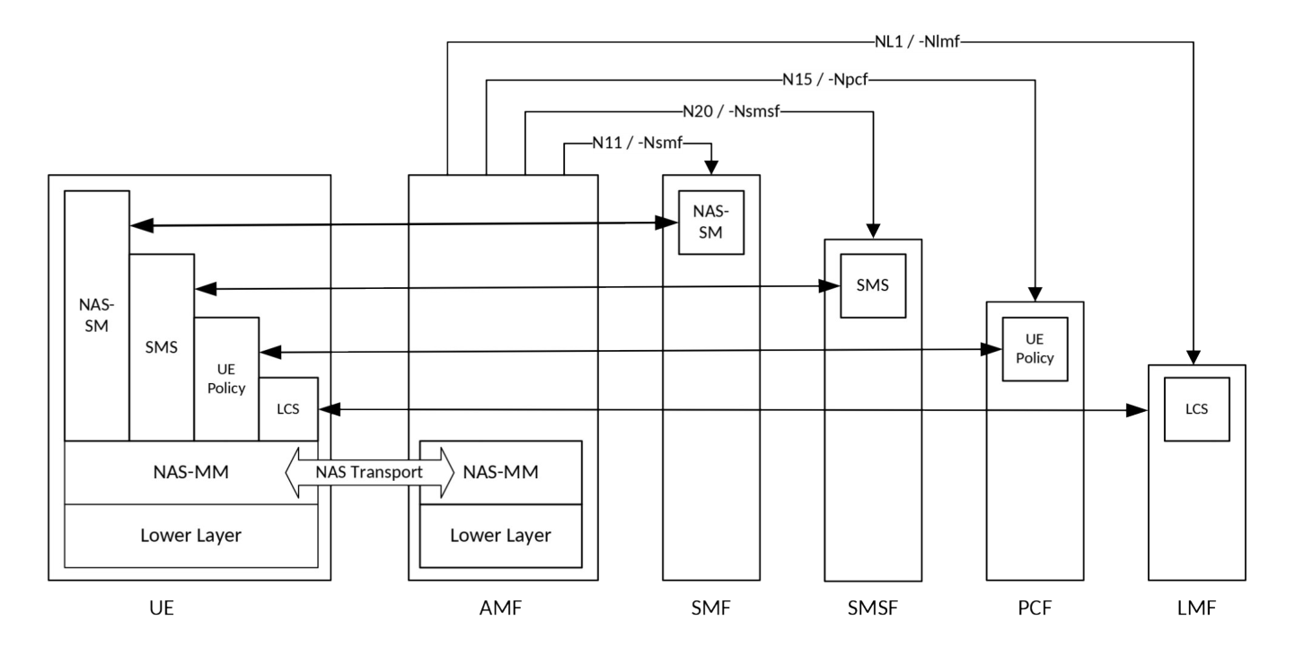
The carrying message holds three things: what type the payload is, extra information the receiving side needs to work out where to forward it, and the payload itself §8.2.2.1.
Registration and connection management messages and these other types are decoupled — the AMF decides on its own part without looking at whatever else was bundled in the same message.
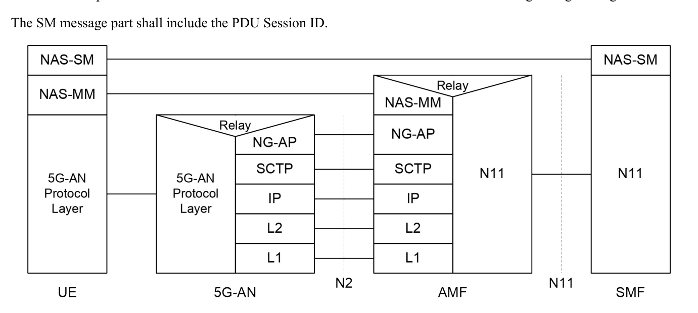
The relay symbol at the AMF is the whole point of the figure.
The sending side builds a NAS-MM message with a security header saying this is transport of session management signalling; the receiving side checks integrity on the NAS-MM part and reads the routing information, and never interprets the content §8.2.2.3.
That identifier is what makes the forwarding possible at all — see Every name the system uses. Registration itself is Registration, reachability and paging.
8.4 The two stacks the document declines to draw
Between core functions, clause 8 has two sentences and no figures.
-
The protocols for the service-based interfaces listed in §4.2.6 are defined in TS 29.500 §8.2.3.1.
-
The protocol for N4, between the SMF and the UPF (the function that forwards user packets), is defined in TS 29.244 §8.2.3.2.
The name PFCP for the N4 protocol appears once in the whole document, in a note about exposing user-plane information §4.2.16, and never in clause 8.
8.5 The user plane: one tunnel per PDU session
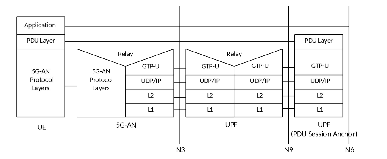
Four layers, top down §8.3.1:
-
PDU layer — the payload the device and the data network actually exchange over the PDU session. For session type IPv4, IPv6 or IPv4v6 these are IP packets; for session type Ethernet they are Ethernet frames.
-
GTP-U — the tunnel, defined in TS 29.281. It carries all end-user PDUs on N3, between the access node and the UPF, and on N9, between UPFs. The legend also says this protocol is used on N4.
-
UDP and IP — described in the legend as simply the backbone network protocols.
-
L2 and L1 — whatever the transport network is made of.
Two facts hide in those three sentences. The tunnel is per session, not per flow and not per device — so a session with several QoS Flows is still one tunnel. And the per-flow quality marking travels in the GTP-U layer, which is why the end-user packet inside is never rewritten. That is What the network promises.
How many UPFs sit in the path is not fixed by 3GPP: zero, one or several non-anchor UPFs may stand between the access node and the anchor, and the one drawn in the figure is optional §8.3.1.
Where the session is split — an uplink classifier or a branching point, both from §5.6.4 — that node is the non-anchor UPF of the figure, with several N9 tunnels branching out of it to different anchors §8.3.1.
N9 may also cross between networks, when a roaming session is routed home §8.3.1. More in Where the packets actually go and The connection to a data network.
8.5.1 Which header each hop adds
Read the figure across, and the encapsulation is easy to follow.
| Segment | What is on the wire, top down |
|---|---|
| Device to access node | PDU layer, then the access network's own protocol layers |
| N3, access node to UPF | PDU layer, GTP-U, UDP and IP, L2, L1 |
| N9, UPF to UPF | the same as N3 |
| N6, anchor UPF onwards | PDU layer — the tunnel has ended |
The access node and any non-anchor UPF are marked "Relay" in the figure. They do not terminate the PDU layer; they carry it from one lower stack into another. The PDU layer runs unbroken from the device to the anchor.
8.5.2 What the encapsulation costs
Clause 8 never gives a byte count, so any number you have in mind came from somewhere else. What it does say is where things break instead: large NAS messages may be fragmented by the inner IP layer or by TCP §8.2.4 §8.2.5, and large GRE packets by the inner IP layer §8.3.2 §8.3.3.
GRE is a way of wrapping one packet inside another. Both cases are non-3GPP access, and both are the same warning — add enough headers and something below you has to cut the packet up.
8.6 Non-3GPP access stacks the layers deeper

Reaching the core over untrusted non-3GPP access — a public Wi-Fi network, say — puts a gateway called the N3IWF in front of the UPF. The user plane between device and gateway becomes GRE inside an inner IP layer inside an IPsec tunnel (an encrypted tunnel) inside ordinary IP inside the non-3GPP access.
From the gateway onward it is the N3 and N9 stacks above, unchanged §8.3.2. Trusted non-3GPP access has the same shape with a TNGF in place of the N3IWF §8.3.3.
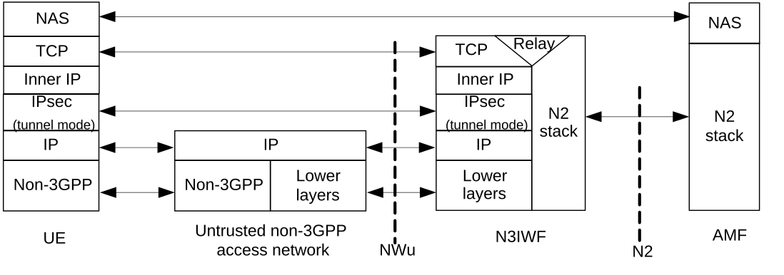
The control plane over untrusted access has two states, before and after the signalling IPsec security association exists.
Afterwards, NAS rides on TCP over the inner IP layer over IPsec, and the gateway relays it into the N2 stack §8.2.4. Trusted access again matches, with an NWt connection instead §8.2.5.
In both, UDP may be inserted to get IPsec and IKEv2 — the exchange that sets an IPsec tunnel up — through address translation §8.2.4 §8.2.5.
Three shorter cases finish the clause:
-
Wireline access is not described here at all — both planes are handed to TS 23.316 §8.2.6 §8.3.4.
-
A device that cannot speak 5G itself, reaching the core over trusted WLAN, uses EAP only to authenticate onto that WLAN, and a transport layer between it and the interworking function §8.2.7 §4.2.8.5.4. In this release only IP sessions are supported for it §8.3.6.
-
N19 forwarding inside a virtual network group is a shared user-plane tunnel joining two anchor UPFs §8.3.5.
The access networks themselves are Radio, Wi-Fi, cable — every way in, and what the IPsec and NAS security are protecting is Who you are and who may listen.
Check yourself
Answers appear when you pick one, with where they come from.
Q8.1 What sits directly under NGAP on N2, between the access network and the AMF?
The legend of the N2 stack names SCTP, which guarantees delivery of signalling messages between the AMF and the access node. §8.2.1.2
Q8.2 A phone is served by one AMF over 3GPP access and non-3GPP access at the same time. How many N1 NAS signalling connections does it have?
A single N1 connection is used for each access the UE is connected to, even when a single AMF serves both. §8.2.2.1
Q8.3 What does the AMF do with the session-management part of a NAS message?
The SM message is created and processed in the NAS-SM layers of the UE and the SMF. The AMF handles only the NAS-MM part around it. §8.2.2.3
Q8.4 At what granularity does GTP-U encapsulate user traffic on N3 and N9?
The legend says GTP encapsulates all end user PDUs and provides encapsulation on a per PDU Session level. The QoS Flow marking rides inside that same layer. §8.3.1
Q8.5 Which protocol does TS 23.501 name for the service-based interfaces?
Clause 8 gives the service-based interfaces one sentence, and that sentence hands the whole stack to TS 29.500. §8.2.3.1
Q8.6 On untrusted non-3GPP access, what may fragment a large NAS message?
Once the signalling IPsec security association is up, NAS rides on TCP over an inner IP layer, and either of those two may fragment. §8.2.4
This chapter was written against TS 23.501 version 20.2.0, verified 2026-08-04. A newer version of the document may say something else.