3GPP 23.501 v20.2.0 — the document's own text
8.3.1 User Plane Protocol Stack for a PDU Session
Taught in 8. What actually travels on the wire (The 5G system architecture, in depth), 1. What this document actually describes (The 5G system architecture, overview).
This clause illustrates the protocol stack for the User plane transport related with a PDU Session.
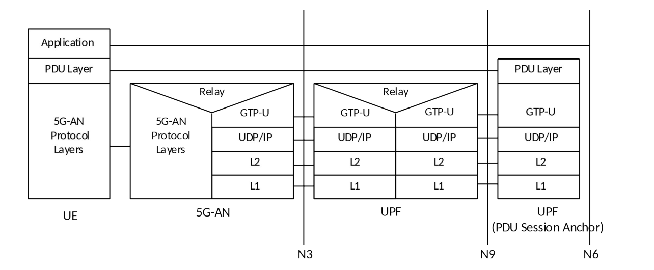
Legend:
- PDU layer: This layer corresponds to the PDU carried between the UE and the DN over the PDU Session. When the PDU Session Type is IPv4 or IPv6 or IPv4v6, it corresponds to IPv4 packets or IPv6 packets or both of them; When the PDU Session Type is Ethernet, it corresponds to Ethernet frames; etc.
- GPRS Tunnelling Protocol for the user plane (GTPU): This protocol supports tunnelling user data over N3 (i.e. between the 5G-AN node and the UPF) and N9 (i.e. between different UPFs of the 5GC) in the backbone network, details see TS 29.281 [75]. GTP shall encapsulate all end user PDUs. It provides encapsulation on a per PDU Session level. This layer carries also the marking associated with a QoS Flow defined in clause 5.7. This protocol is also used on N4 interface as defined in TS 29.244 [65].
- 5G-AN protocol stack: This set of protocols/layers depends on the AN:
- When the 5G-AN is a 3GPP NG-RAN, these protocols/layers are defined in TS 38.401 [42]. The radio protocol between the UE and the 5G-AN node (eNodeB or gNodeB) is specified in TS 36.300 [30] and TS 38.300 [27].
- When the AN is an Untrusted non 3GPP access to 5GC the 5G-AN interfaces with the 5GC at a N3IWF defined in clause 4.3.2 and the 5G-AN protocol stack is defined in clause 8.3.2.
- UDP/IP: These are the backbone network protocols.
NOTE 1: The number of UPF in the data path is not constrained by 3GPP specifications: there may be in the data path of a PDU Session 0, 1 or multiple UPF that do not support a PDU Session Anchor functionality for this PDU Session.
NOTE 2: The "non PDU Session Anchor" UPF depicted in the Figure 8.3.1-1 is optional.
NOTE 3: The N9 interface may be intra-PLMN or inter PLMN (in the case of Home Routed deployment).
If there is an UL CL (Uplink Classifier) or a Branching Point (both defined in clause 5.6.4) in the data path of a PDU Session, the UL CL or Branching Point acts as the non PDU Session Anchor UPF of Figure 8.3.1-1. In that case there are multiple N9 interfaces branching out of the UL CL / Branching Point each leading to different PDU Session anchors.
NOTE 4: Co-location of the UL CL or Branching Point with a PDU Session Anchor is a deployment option.