What the system does · chapter 14 of 27 · 13 minutes
14 What the network promises
How 5G splits a connection into QoS Flows, describes each one with a small set of parameters, and enforces them at the phone, the radio and the core.
14.1 Why a packet network needs a promise at all
A plain IP network treats every packet the same. That is fine when capacity is free. Radio capacity is not free: it is shared, it moves with the weather and the crowd, and it is the scarcest thing in the system.
So the 5G core has to be able to say, for one particular stream of packets inside one connection, what treatment it should get — how fast, how soon, how reliably, and who loses out first when there is not enough to go round.
Clause §5.7 is that language. Everything in it is about describing a stream, labelling its packets, and getting the description to the three places that can actually act on it.
14.2 The QoS Flow is the unit
Inside one PDU session (the connection to a data network, see The connection to a data network) the traffic is split into QoS Flows. Each flow carries a QoS Flow Identifier, the QFI, unique within that session.
The QFI travels in the tunnel header on N3 and N9 — the links from the radio network to the core and between core user-plane nodes — so the end-to-end packet is never touched §5.7.1.1.
The 5QI value itself may be reused as the QFI for a non-GBR flow (GBR is guaranteed bit rate — capacity the network holds open for that flow alone) whose standardised or pre-configured 5QI is below 64. Every other case gets a dynamically assigned QFI §5.7.1.3.
Every PDU session has one flow that is created with it and lives as long as it does: the flow carrying the default QoS rule. It should be a non-GBR flow, so that moving the session to 4G stays possible §5.7.1.1.
14.3 The QoS profile: what the radio network is handed
The SMF (the function that runs sessions) builds a QoS profile per flow and sends it to the radio network through the AMF (the function that keeps track of where a device is and whether it is reachable).
Two parameters are always in it: the 5QI and the ARP. The QFI is not — it travels alongside §5.7.1.2.
The rest depends on the kind of flow:
-
A non-GBR flow may carry the Reflective QoS Attribute (RQA).
-
A GBR flow must carry a guaranteed flow bit rate (GFBR) and a maximum flow bit rate (MFBR), each for uplink and downlink.
-
A GBR flow may also carry notification control and a Maximum Packet Loss Rate, which in this release is only used for voice media §5.7.2.8.
-
Any flow may carry PDU Set parameters, for applications sent as groups of packets that only make sense together §5.7.7.1.
14.4 5QI points at a table, it does not contain one
Three ways to get characteristics to the radio network exist. A standardised 5QI maps one-to-one onto the row in table 5.7.4-1. A pre-configured 5QI maps onto a row the operator loaded into the access node. A dynamically assigned 5QI carries the full set of characteristics inside the QoS profile §5.7.2.1.
Individual characteristics can still be overridden next to a standardised 5QI. Priority level §5.7.3.3, the dynamic core-network delay budget §5.7.3.4, averaging window §5.7.3.6 and maximum data burst volume §5.7.3.7 may each be signalled and then win over the table value.
14.4.1 ARP decides who survives a shortage
The Allocation and Retention Priority is not about scheduling packets. It is about admitting and dropping whole flows when resources run out §5.7.2.2.
It has three fields: a priority level from 1 to 15 with 1 highest, a pre-emption capability (may this flow take resources from a lower-priority one), and a pre-emption vulnerability (may this flow have its resources taken).
Levels 1 to 8 are meant for services the serving network itself has authorised, which is why they are kept clear for things like emergency traffic.
Levels 9 to 15 are the usual ones a home network hands out to a roaming subscriber; 1 to 8 are allowed too where a roaming agreement covers them §5.7.2.2.
14.5 Reading the standardised table
Six characteristics describe a flow §5.7.3.1: resource type, priority level, packet delay budget, packet error rate, averaging window (GBR and delay-critical GBR only) and maximum data burst volume (delay-critical GBR only). Table 5.7.4-1 is a list of agreed combinations §5.7.4.
| 5QI | Resource type | Priority | Delay budget | Error rate | Max burst | Averaging window | Example service |
|---|---|---|---|---|---|---|---|
| 1 | GBR | 20 | 100 ms | 10⁻² | n/a | 2000 ms | Conversational voice |
| 5 | Non-GBR | 10 | 100 ms | 10⁻⁶ | n/a | n/a | IMS signalling |
| 85 | Delay-critical GBR | 21 | 5 ms | 10⁻⁵ | 255 bytes | 2000 ms | High-voltage electricity distribution |
5QI 1 is a voice call. GBR means dedicated resources are held for it. Its error rate of 10⁻² looks careless until you remember that a voice codec would rather lose a packet than wait for it. Priority 20 is high — the standardised values run from 5 to 90, and low means strong.
5QI 5 is IMS signalling — the messages that set a call up. Non-GBR, so nothing is reserved, but priority 10 is much stronger than the voice media it sets up, and the error rate is four orders of magnitude tighter. Signalling must arrive; audio may be slightly lossy.
5QI 85 is an industrial control loop. Delay-critical GBR with a 5 ms budget and a 255-byte burst allowance: the network commits to carrying up to 255 bytes within the access-network share of that 5 ms.
The delay budget is measured between the UE (the phone or other device) and the N6 termination point at the UPF (the core node that hands user traffic to the outside data network), not just over the air.
The radio's own share is that budget minus a core-network delay budget given per row in the table notes: 20 ms for 5QI 1, which leaves 80 ms for the radio, and 2 ms for 5QI 85, which leaves 3 ms §5.7.3.4.
The packet error rate is an upper bound on losses that are not caused by congestion — packets the link layer sent but never delivered upwards. Its purpose is to let the radio configure retransmission and coding §5.7.3.5.
14.6 Bit rates, per flow and per bundle
Per flow, GBR only: the GFBR is what the network guarantees over the averaging window, and the MFBR is the ceiling above which traffic gets shaped, delayed or dropped. Traffic between the two is carried according to the flow's priority level §5.7.2.5.
Three aggregate limits sit above that, and none of them apply to GBR flows except the last §5.7.2.6:
-
Session-AMBR caps the total across all non-GBR flows of one PDU session.
-
UE-AMBR caps the total across all non-GBR flows of one device. Each radio node sets its own UE-AMBR to the sum of the Session-AMBRs it is currently carrying, up to the value the AMF gave it.
-
UE-Slice-MBR caps the total across all flows, GBR and non-GBR, that belong to one device's sessions on one slice — see One network, many networks.
Who enforces which is spelled out in §5.7.1.8:
-
E1. The UPF enforces Session-AMBR and, downlink, the MFBR of GBR flows.
-
E2. The radio network enforces UE-AMBR for non-GBR flows, and the MFBR of GBR flows in both directions.
-
E3. The UE limits its own uplink non-GBR traffic to the Session-AMBR it was given, and on non-3GPP access should enforce the uplink MFBR too.
14.7 Where packets get labelled
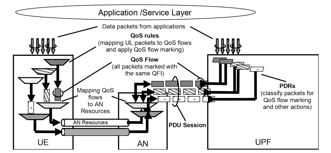
Downlink, the UPF classifies arriving packets against packet detection rules in increasing order of precedence, writes the matching QFI into the tunnel header, and optionally marks the outer IP header for the transport network. A packet matching nothing is discarded §5.7.1.5.
Uplink, the UE does the same job with QoS rules. A QoS rule is a QFI, a packet filter set and a precedence value §5.7.1.4.
Filters match on the usual fields — addresses, ports, protocol, traffic class, flow label, security parameter index, and for Ethernet sessions MAC addresses, ethertype and VLAN tags §5.7.6.2 §5.7.6.3. Rules are evaluated in increasing precedence order, and an unmatched packet is discarded §5.7.1.5.
The radio network then maps flows onto its own resources. There is deliberately no fixed one-to-one relation between QoS Flows and radio bearers: the access network decides how to group them and tells the SMF when it releases them §5.7.1.5.
Packet filters are never used for that mapping — only the QFI and the profile §5.7.1.6. More on the user plane in Where the packets actually go.
14.8 Reflective QoS: letting the phone work it out
Signalling a rule for every stream costs messages. Reflective QoS avoids them: the network marks downlink packets, and the UE builds the matching uplink rule itself §5.7.5.1.
The mechanism is a Reflective QoS Indication bit in the tunnel header next to the QFI, plus a timer value given per PDU session.
On a marked downlink packet the UE derives an uplink filter by mirroring the packet's addresses, ports and protocol, creates a derived rule with the packet's QFI, and starts the timer. Later marked packets restart it; when it expires the rule is deleted §5.7.5.3.
For IP sessions this only works where the protocol is TCP, UDP or ESP; for Ethernet sessions only where 802.1Q tagging is used §5.7.5.2. The radio network only passes the indication through for flows whose profile carried the RQA §5.7.2.3.
14.9 When the promise cannot be kept
Radio conditions change. Notification control tells the radio network: if you can no longer meet the GFBR, the delay budget or the error rate, do not drop the flow — say so and keep carrying it.
The SMF may pass that on to the PCF (the policy function), and an application able to adapt lowers its rate §5.7.2.4.1a.
The notification names a direction when only one direction is affected, and the reverse message, "GFBR can again be guaranteed", is only sent when every one of the three is met in both directions again §5.7.2.4.1a.
Alternative QoS profiles make that more useful. The SMF may hand the radio network a ranked list of fallback combinations of GFBR, delay budget, error rate and averaging window that the application can live with.
When the main profile fails, the radio network reports which entry in the list it is actually meeting, rather than only that it failed §5.7.1.2a §5.7.2.4.1b.
The same list is used at handover: a target node that cannot meet the profile accepts the flow anyway if it can meet one of the alternatives, instead of rejecting it §5.7.2.4.2.
Unless policy says otherwise, the SMF then tells the UE over NAS signalling (the messages that run between the device and the core, not the radio) which 5QI, GFBR and MFBR are actually in force §5.7.2.4.1b.
14.10 Measuring what was really delivered
A promise nobody checks is decoration. QoS monitoring measures a running flow and reports the result. An application function asks, the PCF authorises it into a policy rule, and the SMF configures the UPF and, where needed, the radio network §5.45.1.
Four things are measured directly here:
-
Packet delay — uplink, downlink or round trip, between UE and the anchor UPF §5.45.2.
-
Congestion — a percentage congestion level per flow, reported by the radio network to the UPF. This is mutually exclusive with ECN marking for L4S (a congestion flag set in the packet header so the sender slows down before anything is dropped) on the same flow §5.45.3.
-
Data rate — measured at the anchor UPF over a standardised window, for GBR and non-GBR flows alike §5.45.4.
-
Available bitrate — for a GBR flow without alternative QoS profiles, how much the radio network could give it. Reporting is threshold-based, never periodic, and travels to the UPF inside the header of uplink packets §5.45.6.
Monitoring only happens where both ends can do it: the AMF tells the SMF whether the radio nodes in the area support it, and the SMF combines that with what the UPF supports §5.45.1.
14.11 Where this meets the rest of the system
The parameters in this chapter do not come from nowhere. They are derived from policy rules — see Rules, and paying for them — and the SMF's job is to bind those rules to flows and translate them into a profile, a set of UE rules and a set of UPF rules §5.7.1.5.
When there is no dynamic policy at all, the SMF falls back on subscription values and local configuration §5.7.2.7.
Roaming adds a second opinion: the visited network may set constraints on the 5QI, priority and ARP of the default flow and on the session's maximum rate, and may remap or downgrade values it does not accept §5.7.1.11. That is Being served by somebody else's network.
Slices carry their own rate limit through UE-Slice-MBR §5.7.1.10. The PDU Set parameters that override the delay budget §5.7.7.2 and the error rate §5.7.7.3 for frame-based media belong to Very fast, very reliable, very picky.
Check yourself
Answers appear when you pick one, with where they come from.
Q14.1 What is the finest thing 5G can give a separate quality treatment to?
All traffic marked with the same QFI inside one PDU session gets the same forwarding treatment, so the flow is the unit — not the session and not the packet. §5.7.1.1
Q14.2 What does a 5QI value actually carry?
A 5QI is a scalar used as a reference to the characteristics in the standardised table. Bit rates are separate parameters. §5.7.2.1
Q14.3 In the ARP priority level, which end of the range 1 to 15 is the important one?
The range is 1 to 15 with 1 as the highest priority, and levels 1 to 8 are meant for services the serving network has authorised. §5.7.2.2
Q14.4 Session-AMBR limits the total bit rate across which flows of a PDU session?
Session-AMBR caps the aggregate across all non-GBR QoS Flows of the session and is explicitly not applicable to GBR QoS Flows. §5.7.2.6
Q14.5 A phone has an uplink packet that matches none of its QoS rules. What happens?
For IP and Ethernet sessions the rules are evaluated in precedence order, and if no rule matches, the UE discards the uplink packet. §5.7.1.5
Q14.6 With notification control on, what does the radio network do when it can no longer meet the guaranteed bit rate?
The point of notification control is that the flow survives the bad patch while the application is told to adapt. §5.7.2.4.1a
This chapter was written against TS 23.501 version 20.2.0, verified 2026-08-04. A newer version of the document may say something else.