Special worlds · chapter 23 of 27 · 14 minutes
23 Very fast, very reliable, very picky
How 5G duplicates traffic for machines that cannot lose a packet, and how it learns to see video frames instead of packets for headsets and games.
23.1 Two workloads the ordinary promises cannot describe
The quality language of What the network promises describes a stream with averages: a delay budget, an error rate, a bit rate, a priority. Enough for a voice call, more than enough for a download.
Two workloads break it, and clause §5.33 and clause §5.37 are the two answers.
The first is a machine that must not lose a packet — a robot arm, a switch in a substation. It asks for very little bandwidth. It asks that the packet arrive when a radio link, a cable or a whole base station has just failed.
The second is a headset. Extended reality, cloud gaming, touch feedback §5.37.1. A video frame is not one packet, it is a burst of them, and half a frame is worth nothing. The network's unit of work is smaller than the application's unit of meaning.
Neither answer invents a new radio. Both add descriptions, so the parts already there can decide better.
23.2 Reliable means the same packet twice, on two paths
Clause §5.33 lists exactly one feature for ultra reliable low latency: redundant transmission §5.33.1. Everything else in the clause is measurement.
Two house rules come with it. In this release it applies to 3GPP radio only, not to Wi-Fi. And when a session is going to carry such traffic, the device and the SMF (the function that sets up a connection) should make it an always-on PDU session §5.6.13, so the tunnel never has to be rebuilt in a hurry.
The clause then offers three levels of duplication. They differ in how far up the stack the two copies are made, and therefore in what kind of failure they survive.
23.2.1 Level one: two sessions, two paths, two anchors
The device sets up two PDU sessions and the network keeps their user plane paths disjoint: one through the master radio node to one anchor UPF, one through the secondary radio node to another §5.33.2.1.
That two-node picture is the document's own example, and one radio node may carry both sessions instead §5.33.2.1. The subscription in the UDM (the store of what a subscriber is allowed) says whether the device may do this at all.
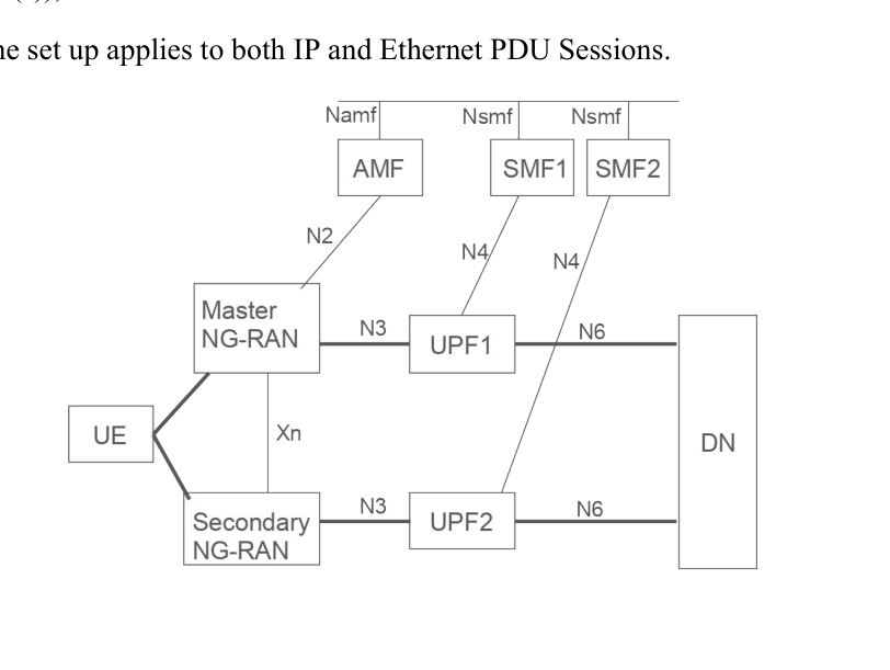
Two small identifiers carry the whole request. The RSN differentiates the two sessions, and the PDU Session Pair ID says they belong together. The device may put both in its establishment request, or the SMF derives them from the S-NSSAI, the DNN and local configuration §5.33.2.1.
The device gets its side from URSP rules (the rules in the phone that decide which connection an app's traffic uses): two rules with distinct traffic descriptors, differing in DNN, IP descriptor or non-IP descriptor such as a MAC address or VLAN ID. A device may also do it without URSP at all.
The radio still decides. The core asks for dual connectivity by sending the RSN and the pair ID; the radio node reads them together with its own configuration and sets it up if it can. If it cannot, the session is established anyway, without the redundancy, and each session is judged on its own §5.33.2.1.
That sentence is the point of the level: 5G builds two pipes and hands them over. Copying a frame into both and dropping the second arrival is somebody else's job, typically IEEE 802.1CB frame replication in the device's operating system and in the factory network.
23.2.2 Level two: two tunnels inside one session
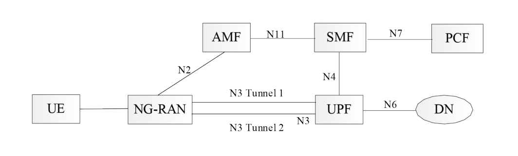
Sometimes the radio node, the UPF and the control functions are reliable enough, and only the backhaul between them is not. Then two N3 tunnels are set up for a single PDU session, over transport paths that do not share fate §5.33.2.2.
Here the copying is the network's own work, per QoS Flow: both tunnels carry the same QFI, the number that marks which flow a packet belongs to.
Downlink, the anchor UPF replicates each packet and gives both copies the same GTP-U sequence number — GTP-U is the tunnel protocol the core carries user packets in. The radio node drops the second copy it sees, uplink is the mirror image, and reordering is explicitly not required of the receiver.
Two intermediate UPFs may sit on the legs, turning it into two N3 and two N9 tunnels. Those intermediate UPFs may not act as an uplink classifier or a branching point §5.33.2.2 — a fork inside a fork would break the pairing.
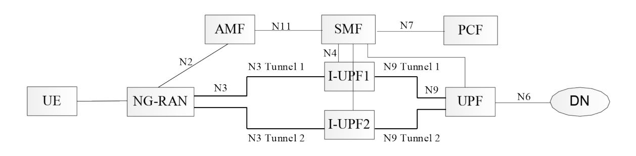
The SMF decides whether to switch duplication on, from the authorised 5QI (the number pointing into a table of delay, loss and priority values), the radio node's capability and operator configuration.
It may also use Redundant Transmission Experience analytics from the NWDAF (the function that does network analytics) to decide when to start or stop. If the device moves to a radio node that does not support this, the SMF may release the flow.
23.2.3 Level three: two paths beneath the tunnel
The cheapest level. One GTP-U tunnel, with the duplication happening in the transport layer beneath it over two disjoint backhaul paths. No 3GPP protocol changes; the SMF only has to pick a UPF that supports it, from configuration or from what the UPF reported at N4 association setup §5.33.2.3.
23.3 Measuring the delay you promised
Promising a delay is easy; knowing you kept it is clause §5.33.3. The delay between device and anchor UPF is measured in two halves: the radio part, and the part between radio node and anchor §5.33.3.1.
An application function can ask for it through the PCF, or the operator turns it on by policy.
The per-flow method works like a ping with four timestamps §5.33.3.2. The anchor UPF sends a monitoring packet marked with a QoS Monitoring Packet indicator and its send time T1.
The radio node records T1 and its arrival time T2, then puts T1, T2, its send time T3 and the measured radio delay into the GTP-U header of an uplink packet — a dummy one if no real uplink packet is due. The UPF records T4.
If the two ends share a clock, the two directions are read separately from T2−T1 and T4−T3. If they do not, the UPF uses (T2−T1+T4−T3)/2 and treats both directions as equal, which the clause itself flags as inaccurate.
The cheaper method measures whole GTP-U paths instead of single flows §5.33.3.3. A sender estimates round-trip time with GTP-U Echo messages, halves it, adds its own processing time and any accumulated delay from the sender before it.
What arrives at the anchor is then an estimate of the time since the packet entered the 3GPP domain. Crossing a threshold raises an alert to the SMF or to the management system.
The same readings, taken per network instance and per DSCP value — DSCP is the priority marking IP routers between the boxes read — let the SMF move flows onto a better transport path.
23.4 The PDU Set: teaching the network what a frame is
Now the picky traffic. Clause §5.37 starts from a single new object.
Three parameters describe one, and they live in the QoS profile beside the ordinary ones §5.7.7.1.
-
PDU Set Delay Budget (PSDB) — the time from the first packet of the set arriving to the last one having been delivered. Not per packet: per set. Where it is present it supersedes the ordinary packet delay budget §5.7.7.2.
-
PDU Set Error Rate (PSER) — the share of sets that the link layer sent but did not deliver whole. A set counts as delivered only when every packet in it arrived §5.7.7.3.
-
PDU Set Integrated Handling Information (PSIHI) — a yes or no: does the application need all the packets of the set, or can it use a partial one §5.7.7.4?
A PCC rule turns the feature on by carrying at least a PSIHI, or at least both a PSDB and a PSER §5.7.7.1.
23.4.1 Marking the packets so the radio can see the set
Parameters describe the shape; the radio still has to know which packet belongs to which set. The anchor UPF works that out and writes PDU Set Information into the GTP-U header of every downlink packet §5.37.5.2:
-
the PDU Set sequence number, unique within the flow,
-
a flag on the last packet of the set,
-
the packet's own sequence number inside the set,
-
the size of the set in bytes,
-
the PDU Set Importance, which ranks this set against other sets of the same flow.
Under congestion the radio may discard at set level rather than packet level, using the Priority Level §5.7.3.3 to choose between flows and the importance to choose within one.
The same importance may also steer transport level marking, though the clause recommends it only vary drop precedence in the routers between core and radio, since more would reorder the flow §5.8.2.7.
How does the UPF find a frame boundary in a byte stream? The application function supplies a Protocol Description: RTP or SRTP, with or without header extensions, with or without a named payload format such as H.264 or H.265, or Media over QUIC, or a UDP option §5.37.5.1.
Uplink is left to the device; the SMF may pass it the uplink description, and using it is optional.
Radio nodes do not all support this. The radio reports a PDU Set Based Handling Support Indication, and after a handover the SMF switches the marking in the UPF to match §5.37.5.3. When it switches on it must begin at a set boundary, never mid-set.
23.5 Bursts, sleep, and congestion the application can act on
Frames arrive in bursts, and a burst has a shape the radio can exploit. The core passes the uplink and downlink periodicity and the measured N6 jitter to the radio inside TSCAI — the description of when each burst will arrive, borrowed from Clocks, TSN and deterministic delivery §5.27.2.
The radio can then put the device to sleep between bursts with connected mode discontinuous reception §5.37.8.2. The jitter figure says how far the first packet of a burst may drift from where the periodicity said it would be.
Three more markings sharpen that. The anchor UPF may flag the last packet of a burst §5.37.8.3, may put the burst's size in the header of its first packets §5.37.10.1, and may say how long the gap to the next burst will be §5.37.10.2.
That last one is offered only where the deployment's jitter is small enough for the number to mean anything.
Congestion is handled the other way round: the network tells the application instead of reacting itself. L4S — a scheme in which routers mark packets instead of dropping them — sets the ECN bits, the two congestion bits in the user's own IP header, so the endpoints lower their rate §5.37.3.1.
It is enabled per QoS Flow and per direction, for GBR and non-GBR flows alike, and marking happens in the radio, in the anchor UPF, or in the N3IWF or TNGF when the device came in over Wi-Fi §5.37.3.4.
When the UPF does the marking it is not measuring anything itself: the radio reports a percentage of packets to mark, in a GTP-U header extension, and the UPF converts that to markings however it likes §5.37.3.3.
If a handover lands on a radio node that cannot do either job, the SMF switches to the other place, and if neither can, the application function is told the feature has stopped §5.37.3.1.
23.6 What else the network will tell the application
Clause §5.37.4 is a list of readings an application function may subscribe to: congestion level, uplink and downlink data rate, round trip delay, and for a GBR flow the bitrate actually available §5.37.4.
Clause §5.37.6 turns round trip delay into policy. The application states one round trip requirement; the PCF splits it into an uplink and a downlink packet delay budget, unequal if it likes but summing to no more than the requirement, and writes two PCC rules with two 5QIs.
Monitoring then runs in both directions, and the PCF can re-split the budget as conditions change §5.37.6.
Two smaller controls matter for a headset. A Multi-modal Service ID ties the video, audio and haptic flows of one service together, so the PCF and the radio treat them as one experience rather than three unrelated streams §5.37.2.
And a flag asks the radio to recommend an uplink bitrate, which lets the headset's encoder drop its quality before the air runs out instead of after §5.37.12.
Two more are bookkeeping: packet delay variation is reported alongside the delay itself §5.37.7.1, and individual media flows multiplexed on one transport connection can be told apart §5.37.11.
23.7 When the network cannot see inside the packet
All of the above assumed the UPF can read the media. It cannot when the connection between device and application server is encrypted end to end, so the server sends the media information alongside the traffic instead, over N6 §5.37.9.1.
Three carriers are defined: Media over QUIC with a relay in the UPF §5.37.9.2, connect-UDP to an HTTP/3 proxy at the server §5.37.9.3, and a UDP option §5.37.9.4.
All three carry the same five items — PDU Set Information, end of data burst, expedited transfer indication, data burst size and time to next burst — downlink only, and only between a device and a server, never device to device.
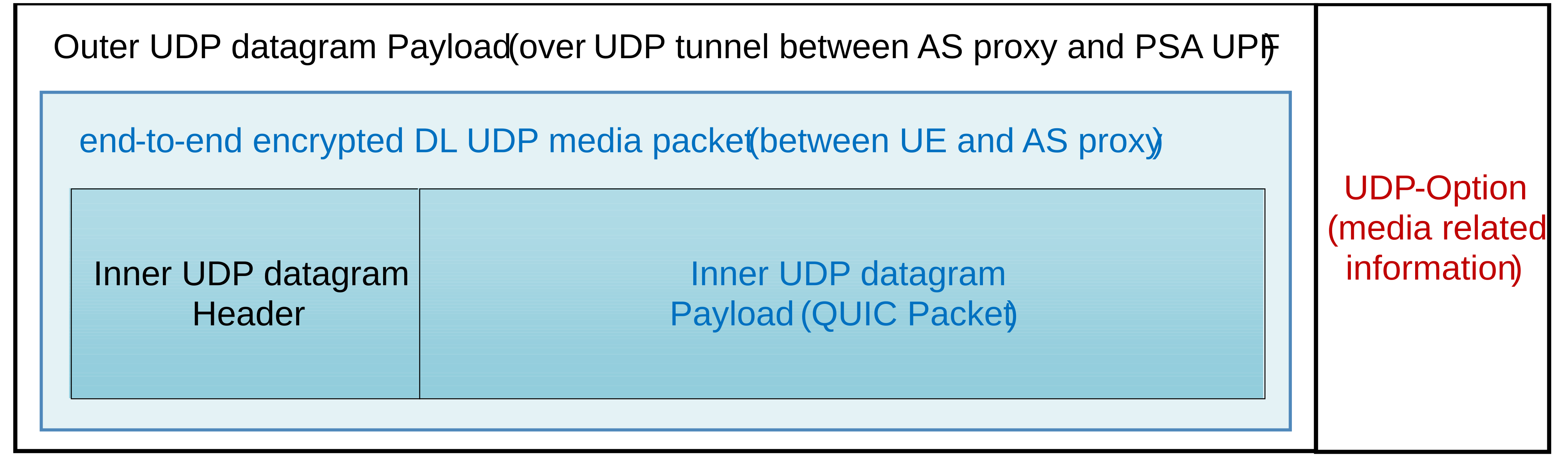
§Annex W draws the UDP option case. The outer datagram, between server proxy and UPF, carries the media information in a UDP option; the inner one is the untouched encrypted packet for the device.
Keys are negotiated when the connect-UDP tunnel is set up, and the UPF strips the option before forwarding the packet §5.37.9.4.
23.8 Annex O: one device, several groups, several promises
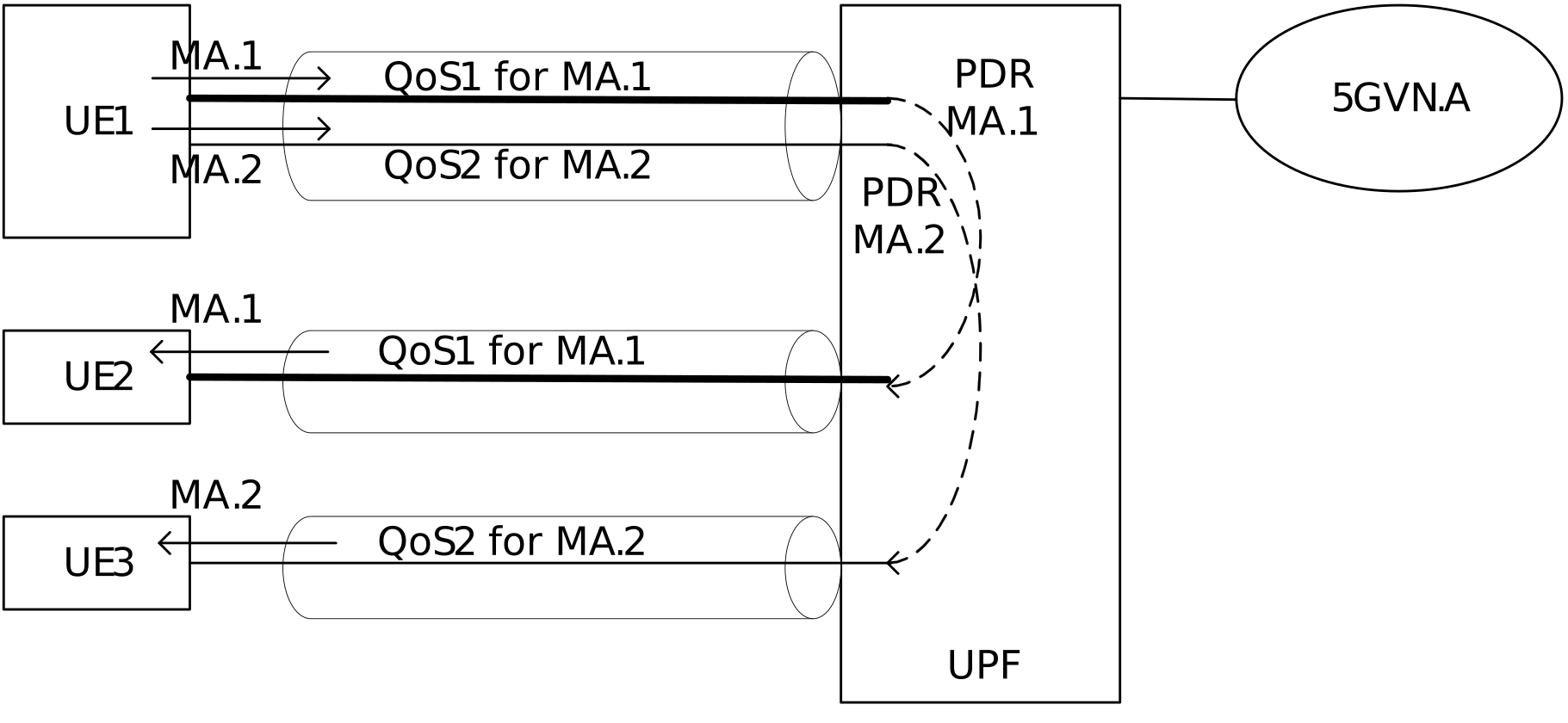
A device in a 5G LAN group — see Networks that are not for everybody — may need to send to several multicast groups at once, each with its own quality §Annex O. The annex gives three deployment patterns and no new mechanism:
-
O.1 — one PDU session, one QoS Flow per group, all under the same DNN and S-NSSAI §O.1.
-
O.2 — one PDU session per group, because the groups sit in different 5G VN groups with different DNN and S-NSSAI combinations §O.2.
-
O.3 — one predefined group made of sub-groups. Traffic to the combined address travels on whichever of the device's flows has the strictest quality of the sub-groups it belongs to §O.3.
23.9 Where this meets the rest
The parameters live in the QoS profile of What the network promises and travel in the GTP-U headers of Where the packets actually go.
Every switch here is thrown by a PCC rule from the PCF — Rules, and paying for them — and most start as an application function's request, which is Computing close by, and opening the door.
TSCAI, borrowed here for power saving, belongs to Clocks, TSN and deterministic delivery, and the dual connectivity clause §5.33 leans on is Radio, Wi-Fi, cable — every way in.
Check yourself
Answers appear when you pick one, with where they come from.
Q23.1 A device sets up two redundant PDU sessions. What tells the radio network that those two belong together?
The PDU Session Pair ID identifies the two sessions as a pair; the RSN is what tells them apart, so the radio gives each one different user plane resources. §5.33.2.1
Q23.2 With two N3 tunnels carrying the same QoS Flow, how does the receiver throw away the copy?
The sender replicates the packet and gives both copies the same GTP-U sequence number; the receiver eliminates on that number, and no reordering is required. §5.33.2.2
Q23.3 What must a PCC rule carry before the radio will do PDU Set based QoS handling?
At least a PSIHI, or at least both a PSDB and a PSER, has to be sent. The PDU Set Size is carried per packet in the GTP-U header, not agreed in a rule. §5.7.7.1
Q23.4 When the anchor UPF does the ECN marking for L4S, where does it learn that the radio is congested?
The radio reports the percentage of packets the UPF should mark; if there is no uplink packet to carry the report, the radio may make a dummy one. §5.37.3.3
Q23.5 Why would an application server put media information into a UDP option on the way to the UPF?
The inner datagram is the encrypted packet between server and device; the outer one carries the media information the UPF would otherwise have had to read out of the payload. §Annex W
This chapter was written against TS 23.501 version 20.2.0, verified 2026-08-04. A newer version of the document may say something else.