What the system does · chapter 11 of 27 · 13 minutes
11 Using two accesses at once
How one connection can run over the mobile radio and Wi-Fi at the same time, and how the network decides which packets go which way.
11.1 Why one connection should be able to use both radios
A phone usually has two ways to reach the internet at once: the mobile radio and Wi-Fi. Left alone, the operating system picks one per socket. When Wi-Fi fades in a stairwell the connections on it break, and the app starts again on the radio — new address, new handshake, visible stall.
Clause §5.32 takes that decision away from the device's own guesswork and makes it something the network can describe, stream by stream.
ATSSS is short for access traffic steering, switching and splitting. It is optional for both the device and the core §5.32.1.
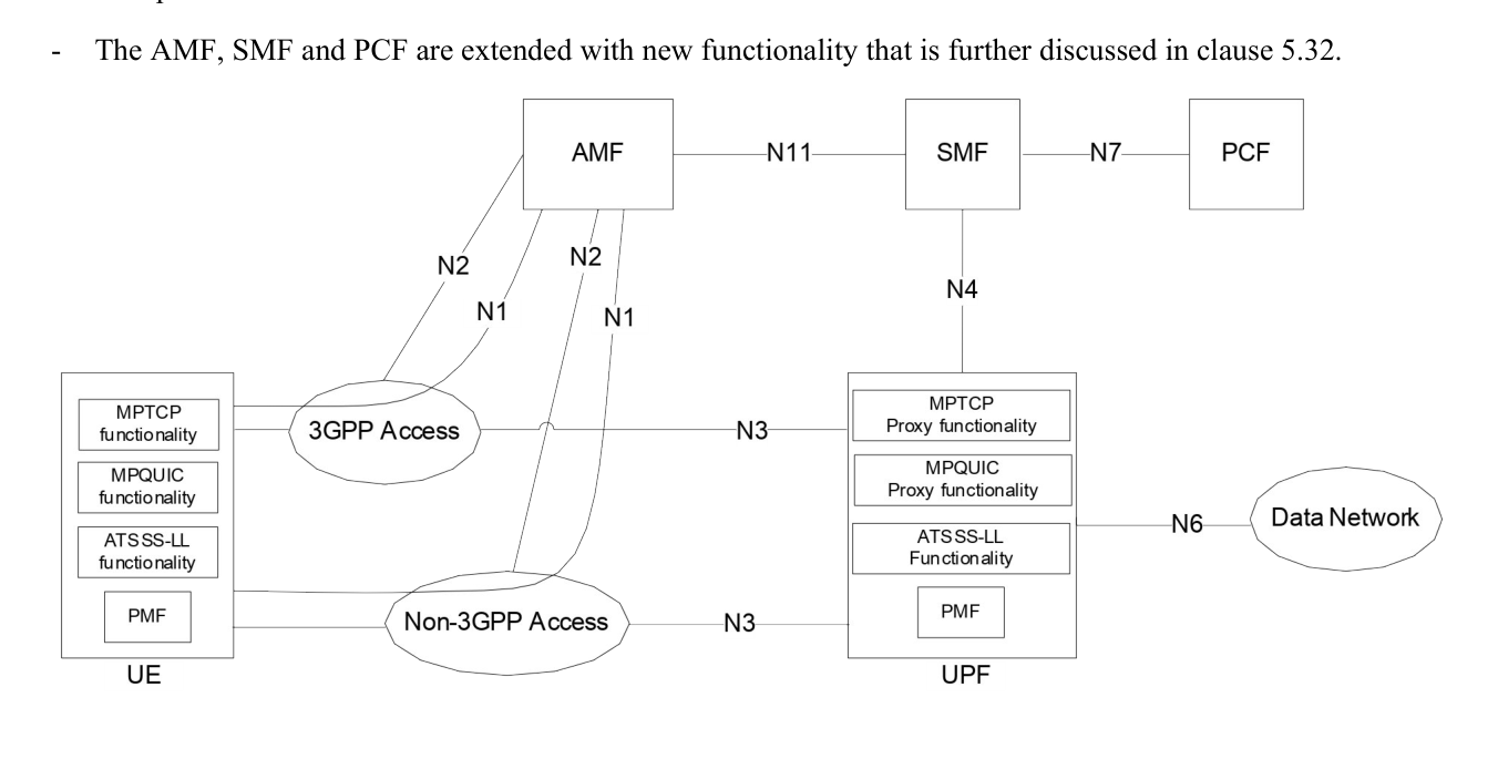
The UE is the phone or device; the PSA is the UPF that anchors the session, the one core node all the packets pass through. N3 and N9 are the two carrying pipes named above: N3 runs from the access network into the core, N9 between core nodes.
11.2 The multi-access PDU session
Everything runs inside one PDU session — the connection to a data network of The connection to a data network — set up the ordinary way with a few additions §5.32.2.
The device sends a PDU Session Establishment Request. The Request Type "MA PDU Request" does not sit in that request itself but in the UL NAS Transport message that carries it — NAS is the signalling a device exchanges with the core, passed straight through the access network §5.32.2.
Which requests are needed depends on where the device is registered, and there is a fourth way in that the device never asks for:
-
Registered to the same network over both accesses: one request is enough. The AMF (the function that tracks where a device is) tells the SMF (the function that runs sessions) that both accesses are there, and both tunnels are built.
-
Registered to different networks over the two accesses: one request over each access, carrying the same PDU Session ID both times.
-
Registered over one access only: one request, one tunnel. The second access is added later, with another request carrying the same session ID.
-
Not asked for at all: the device requested an ordinary single-access session and the network decided to make it multi-access instead. This is optional, and open only when no policy rule and no local setting in the device insists on one access §5.32.2.
In the establishment request the device declares its ATSSS capabilities — which steering functionalities and which steering modes it can do §5.32.2.
That list is an offer, not a decision. The SMF settles what the session may actually do, weighing the offer against the configuration held for the DNN — the name of the data network the session connects to §5.32.2.
The session type may be IPv4, IPv6, IPv4v6 or Ethernet. Unstructured is not supported in this release, and neither is a multi-access session using IPv6 multi-homing or an uplink classifier §5.32.1.
A requested slice must be allowed on both accesses, or the session is not established, which is where One network, many networks comes in. A local area data network is refused outright: the AMF rejects a multi-access request for a LADN DNN §5.32.1.
Once it exists, the session may have user-plane resources on both accesses, on one, or on neither — and the AMF, SMF, PCF and UPF keep its context even when the device deregisters from one of the two §5.32.2.
11.3 How the rules reach the two ends
The decision is written down twice, once for each direction of travel — and the two halves need not say the same thing.
The PCF (the function that holds the policy rules, see Rules, and paying for them) puts MA PDU Session Control information into a PCC rule.
The SMF turns that into two things: ATSSS rules, sent to the device over NAS signalling and applied to uplink traffic, and N4 rules, sent to the UPF and applied to downlink traffic. Without dynamic policy control, the SMF builds both from local configuration §5.32.3.
The device gets a prioritised list of ATSSS rules and evaluates them in order. Each rule has a Rule identifier, a Rule Precedence, a Traffic Descriptor and an Access Selection Descriptor §5.32.8.
The Traffic Descriptor says when the rule applies — application identities, 5-tuples for IP traffic, or non-IP descriptors for Ethernet traffic. A 5-tuple is the five fields that pin down one stream of packets: the two addresses, the two port numbers and the protocol.
A rule may not mix IP and non-IP descriptors. Every component present must match before the rule is used.
The Access Selection Descriptor says what to do: a Steering Mode, optionally a Steering Mode Indicator or Threshold Values (never both), a Steering Functionality, and for the MPQUIC functionalities a Transport Mode.
On the network side the same choices arrive as a Multi-Access Rule, or MAR, which names the steering functionality, the steering mode, the thresholds, and one forwarding action per access with a weight or a priority attached §5.8.5.8.
11.4 The five steering modes
The last column uses GBR, short for guaranteed bit rate: a flow the network has promised a minimum speed to. Everything else is non-GBR.
| Mode | What it does | Traffic it may carry |
|---|---|---|
| Active-Standby | Uses the Active access; switches to the Standby access when Active goes away, and back when it returns. With no Standby defined, the flow is pinned to one access. | Any |
| Smallest Delay | Uses whichever access has the smaller measured round-trip time. If one access goes away, everything moves to the other. | Non-GBR only |
| Load-Balancing | Splits the flow by percentage across both accesses. If one goes away, the other carries 100%. | Non-GBR only |
| Priority-based | Everything on the high-priority access until it is judged congested, then the overflow goes to the low-priority one too. | Non-GBR only |
| Redundant | Sends the same packets over both accesses. A Primary Access may be named, in which case all packets go there and some may be duplicated. | GBR and non-GBR — non-GBR only once a threshold value is given |
How congestion is detected for Priority-based is left to implementation §5.32.8.
Two indicators may soften a Load-Balancing rule. The autonomous load-balance indicator lets the device ignore the network's percentages and pick its own, to get the most out of the two uplinks.
The UE-assistance indicator lets the device depart from them for its own reasons — a low battery, say — and tell the UPF what it chose §5.32.8.
Threshold Values are a maximum round-trip time, a maximum packet loss rate, or both. Under Load-Balancing with fixed percentages, an access whose measurement crosses its threshold gets less traffic or none. Under Priority-based, crossing the threshold is what "congested" may be taken to mean.
Under Redundant, one threshold may be given, and the rule it makes has two strengths: over the loss limit on both accesses, duplicate; over the delay limit on both, duplication is optional. Over the limit on one access, use the other; under the limit on both, use the Primary Access §5.32.8.
11.5 The five steering functionalities
A steering mode says what the split should look like. A steering functionality is the machinery that actually moves the bytes, and each one can carry a different slice of the traffic §5.32.6.1.
-
MPTCP functionality — multipath TCP (RFC 8684) between the device and an MPTCP Proxy in the UPF. TCP traffic only, and never on an Ethernet session.
-
MPQUIC-UDP functionality — UDP traffic, carried inside HTTP/3 over multipath QUIC using the connect-udp method.
-
MPQUIC-IP functionality — the same idea with connect-ip, so it can take all IP traffic, not just UDP.
-
MPQUIC-E functionality — connect-ethernet, and only on an Ethernet session.
-
ATSSS-LL functionality — no protocol at all. This is the one the core may not skip: the UPF must support at least ATSSS-LL with the Active-Standby steering mode §4.2.10.
That last sentence is the trade. ATSSS-LL takes anything and needs no proxy, but it cannot do the Redundant mode, so it cannot duplicate a flow.
The multipath functionalities can, because both ends run a protocol able to number what it carries and put it back in order §5.32.6.2.2.
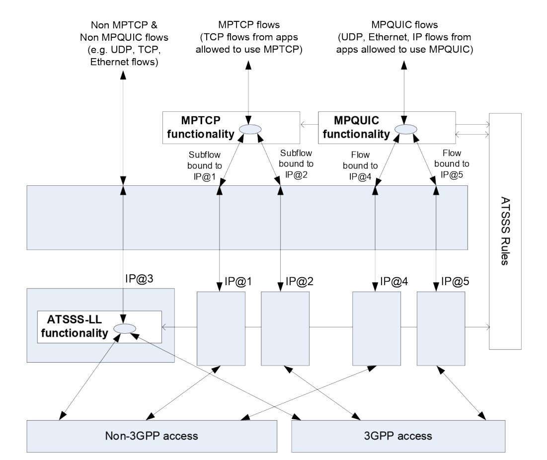
The multipath functionalities need addresses to work with. Besides the session's own address, the network hands the device two extra ones — the "link-specific multipath" addresses, one per access.
The device uses them only towards the proxy; they may not be routable outside, and the proxy uses the session's real address towards the far end §5.32.6.2.1.
An Ethernet session has no session IP address to fall back on that way. The two link-specific addresses are still handed out, and the proxy instead uses the MAC addresses out of the Ethernet frame the device sent when it talks to the far end §5.32.6.2.2.
Inside a QUIC connection, three transport modes are on offer: Datagram mode 2 (no sequence numbers, no reordering), Datagram mode 1 (numbered, reordered and de-duplicated, still unreliable), and Stream mode (reliable and in order).
The document warns against Stream mode for traffic that already retransmits on its own §5.32.6.2.2.
Different flows in one IP session may use different functionalities; one flow may not. An Ethernet session runs either ATSSS-LL or MPQUIC-E, not both §5.32.6.1.
11.6 What the decision rests on
Steering by delay or by loss needs numbers. They come from the Performance Measurement Functionality, the PMF, which sits in the UPF and talks to a matching PMF in the device over the user plane §5.32.5.1.
At session setup the network may send Measurement Assistance Information: for an IP session, one address for the PMF plus one UDP port per access; for an Ethernet session, one MAC address per access.
If per-flow measurement is switched on, there is a port or MAC address per QoS Flow per access as well. ATSSS rules and MAR rules are never applied to PMF messages themselves §5.32.5.1.
What travels:
-
Round-trip time — PMF-Echo Request and Response, sent by both ends. Each side averages its own results; nothing is reported across §5.32.5.2.
-
Packet loss rate — one side asks the other to start counting with a PMF-PLR Count Request, then asks for the tally with a PMF-PLR Report Request, and compares it against what it sent §5.32.5.2a.
-
Access availability — when the device notices an access has gone or come back, it sends a PMF-Access Report and the UPF acknowledges it. How it notices is implementation's business, and the connection-management state of the device does not decide it §5.32.5.3.
-
UE assistance — PMF-UAD carries the split percentages the device chose, PMF-UAT says it has gone back to the network's §5.32.5.5.
-
Suspend and resume duplication — the UPF can tell the device to stop duplicating, for instance when it is congested, and later to start again §5.32.5.6.
When MPTCP or MPQUIC is running alongside ATSSS-LL in Active-Standby, PMF is used only for availability reports: the multipath protocol already knows the delay and the loss §5.32.5.1.
11.7 Quality across two paths
The QoS model of What the network promises is unchanged: the QoS Flow is still the unit, and it is deliberately access-agnostic. The SMF gives both access networks the same QFI — the short number stamped on a packet saying which flow it belongs to — so a packet gets the same treatment either way §5.32.4.
Guaranteed flows are the exception. Splitting a GBR flow is not supported. The SMF gives the QoS profile to one access — to both only under the Redundant steering mode — and when that access goes away it either moves the flow or releases it and tells the PCF §5.32.4.
11.8 Where this touches the rest of the system
The non-3GPP side is whatever Radio, Wi-Fi, cable — every way in allows: untrusted Wi-Fi through an N3IWF, trusted access through a TNGF, wireline §5.32.1. The two tunnels are ordinary N3/N9 user-plane tunnels of Where the packets actually go.
A leg of the session may even run through 4G, the corner of Living next to 4G that clause §5.32 extends §5.32.7.1.
Check yourself
Answers appear when you pick one, with where they come from.
Q11.1 A phone registered on the same network over both radio and Wi-Fi wants a multi-access session. How many establishment requests does it send?
When both registrations are with the same PLMN one request is enough, with Request Type "MA PDU Request" carried in the UL NAS Transport message that conveys it; the AMF tells the SMF the device is on both accesses and both tunnels are set up. Two requests are only needed when the two registrations are with different PLMNs. §5.32.2
Q11.2 Which steering mode sends the same packets over both accesses at once?
Load-Balancing splits traffic by percentage and Priority-based spills onto the second access only when the first is congested. Only Redundant duplicates. §5.32.8
Q11.3 Which steering functionality can carry every kind of traffic but cannot do the Redundant steering mode?
ATSSS-LL applies no protocol of its own and handles TCP, UDP and Ethernet alike, but the specification states it does not support the Redundant Steering Mode. §5.32.6.3.1
Q11.4 How does a round-trip-time measurement get from the phone to the UPF?
Both ends send PMF-Echo Requests and answer each other's, and each derives its own average. There is no reporting of the result from one side to the other. §5.32.5.2
Q11.5 Can a guaranteed-bit-rate flow of a multi-access session be split across the two accesses?
The specification says plainly that traffic splitting is not supported for a GBR QoS Flow; the SMF picks one access, except under the Redundant steering mode where both get the profile. §5.32.4
Q11.6 What does the MPTCP proxy in the UPF use as the source address when it talks to the far-end server?
The two link-specific multipath addresses are used only between phone and proxy and may not be routable on N6. The proxy uses the session's own address towards the final destination. §5.32.6.2.1
This chapter was written against TS 23.501 version 20.2.0, verified 2026-08-04. A newer version of the document may say something else.