3GPP 23.501 v20.2.0 — the document's own text
5.33.2.2 Support of redundant transmission on N3/N9 interfaces
Taught in 23. Very fast, very reliable, very picky (The 5G system architecture, in depth).
If the reliability of NG-RAN node, UPF and CP NFs are high enough to fulfil the reliability requirement of URLLC services served by these NFs, but the reliability of single N3 tunnel is considered not high enough, e.g. due to the deployment environment of backhaul network, the redundant transmission may be deployed between PSA UPF and NG-RAN via two independent N3 tunnels, which are associated with a single PDU Session, over different transport layer path to enhance the reliability. SMF may make use of Redundant Transmission Experience analytics provided by NWDAF, as described in clause 6.13 of TS 23.288 [86], to determine whether redundant transmission for the PDU session of the URLLC shall be performed or (if activated) shall be stopped.
To ensure the two N3 tunnels are transferred via disjointed transport layer paths, the SMF or PSA UPF should provide different routing information in the tunnel information (e.g. different IP addresses or different Network Instances) and these routing information should be mapped to disjoint transport layer paths according to network deployment configuration. The SMF indicates NG-RAN and PSA UPF that one of the two CN/AN Tunnel Info is used as the redundancy tunnel of the PDU Session accordingly. The redundant transmission using the two N3/N9 tunnels are performed at QoS Flow granularity and are sharing the same QoS Flow ID.
During or after a URLLC QoS Flow establishment, if the SMF decided that redundant transmission shall be performed based on authorized 5QI, NG-RAN node capability, operator configuration and/or Redundant Transmission Experience analytics, the SMF informs the PSA UPF and NG-RAN to perform redundant transmission via N4 interface and N2 information accordingly. In this case, NG-RAN should also provide different routing information in the tunnel information (e.g. different IP addresses) and these routing information should be mapped to disjoint transport layer paths according to network deployment configuration.
NOTE 1: The NG-RAN node capability to support the redundant transmission on N3/N9 can be configured in the SMF per network slice or per SMF service area.
If duplication transmission is performed on N3/N9 interface, for each downlink packet of the QoS Flow the PSA UPF received from DN, the PSA UPF replicates the packet and assigns the same GTP-U sequence number to them for the redundant transmission. The NG-RAN eliminates the duplicated packets based on the GTP-U sequence number and then forwards the PDU to the UE.
For each uplink packet of the QoS Flow the NG-RAN received from UE, the NG-RAN replicates the packet and assigns the same GTP-U sequence number to them for redundant transmission. These packets are transmitted to the PSA UPF via two N3 Tunnels separately. The PSA UPF eliminates the duplicated packet based on the GTP-U sequence number accordingly.
NOTE 2: How to realize the sequence number for support of GTP-U duplication over N3/N9 is up to stage 3.
NOTE 3: For redundant transmission on N3/N9 interfaces, reordering is not required on the receiver side.
The PSA UPF and NG-RAN may transmit packets via one or both of the tunnels per QoS Flow based on SMF instruction.
NOTE 4: The AMF selects an SMF supporting redundant transmission based on the requested S-NSSAI and/or DNN.
During UE mobility, when the UE moves from NG-RAN supporting redundant transmission to NG-RAN not supporting redundant transmission, the SMF may release the QoS Flow which are subject to redundant transmission.
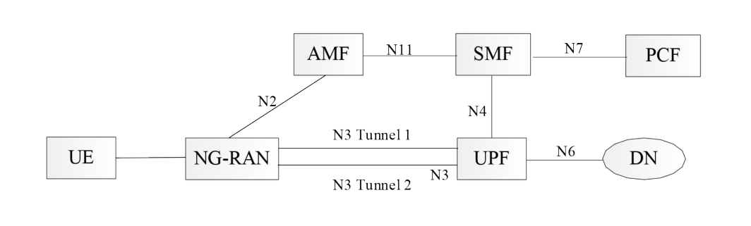
Figure 5.33.2.2-1 illustrates the case that the redundant transmission is performed only on N3 interface. These packets are transmitted to the NG-RAN via two N3 Tunnels separately. The RAN node and PSA UPF shall support the packet replication and elimination function as described above.
Two Intermediate UPFs (I-UPFs) between the PSA UPF and the NG-RAN may be used to support the redundant transmission based on two N3 and N9 tunnels between a single NG-RAN node and the PSA UPF. The NG-RAN node and PSA UPF shall support the packet replication and elimination function as described above.
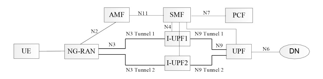
In figure 5.33.2.2-2, there are two N3 and N9 tunnels between NG-RAN and PSA UPF for the URLLC QoS Flow(s) of the same PDU Session for redundant transmission established during or after a URLLC QoS Flow establishment. In the case of downlink traffic, the PSA UPF duplicates the downlink packet of the QoS Flow from the DN and assigns the same GTP-U sequence number to them. These duplicated packets are transmitted to I-UPF1 and I-UPF2 via N9 Tunnel 1 and N9 Tunnel 2 separately. Each I-UPF forwards the packet with the same GTP-U sequence number which receives from the PSA UPF to NG-RAN via N3 Tunnel 1 and N3 Tunnel 2 respectively. The NG-RAN eliminates the duplicated packet based on the GTP-U sequence number. In the case of uplink traffic, the NG-RAN duplicates the packet of the QoS Flow from the UE and assigns the same GTP-U sequence number to them. These duplicated packets are transmitted to I-UPF1 and I-UPF2 via N3 Tunnel 1 and N3 Tunnel 2 separately. Each I-UPF forwards the packet with the same GTP-U sequence number which receives from the NG-RAN to PSA UPF via N9 Tunnel 1 and N9 Tunnel 2 respectively. The PSA UPF eliminates the duplicated packets based on the GTP-U sequence number.
The I-UPFs inserted on one leg of the redundant paths shall not behave in an UL CL or Branching Point role.