The shape of the system · chapter 1 of 7 · 6 minutes
1 What this document actually describes
Which of the three stages TS 23.501 is, what a 5G system is made of, and the design decisions everything else follows from.
1.1 Why anybody wrote a document like this
3GPP describes a telephone system in three passes: what it has to do, how it is put together, and what goes on the wire. TS 23.501 is the middle pass. Its first line says it defines the Stage 2 system architecture for the 5G System §1.
Stage 2 hands out responsibilities. It names the pieces, says what each one owns, and says which pieces talk. It never says what a message looks like.
Two other documents are named in the same clause, and a discussion about 5G walks into them constantly: TS 23.502 holds the procedures and flows, TS 23.503 holds policy control and charging §1.
So when a question stalls on "where is that written", the answer is usually one of the three. This one for who is responsible, TS 23.502 for the order things happen in, TS 23.503 for the rules that decide them.
1.2 The four things in every picture
Every drawing in the document has the same four kinds of thing in it.
-
The UE — the phone, the sensor, the car. The document treats it as part of the architecture, because it holds rules and state the network gave it.
-
The (R)AN — the radio network, or another way in. The brackets are there because the access need not be radio at all.
-
The 5GC — the core: the software functions that decide, authorise, remember and forward.
-
The Data Network — what the user actually wanted: the internet, an operator service, a company network. It is named by a DNN, a Data Network Name.
The user plane path runs UE, radio node, then a tunnel over N3 to a UPF (the function that forwards packets), then out over N6 into the Data Network §8.3.1. The payload is wrapped in GTP-U between the radio node and the core, so the end-to-end packet header is never touched.
1.3 The design brief
The design brief is a quarter of a page, and everything else in the document follows from it §4.1. It was written for operators who wanted to run a core network as software on ordinary servers rather than as a rack of fixed boxes.
The rest of the clause is a list of choices that fall out of that one. The ones worth carrying into every later chapter:
-
Control and user plane are separate, so the deciding parts and the forwarding parts scale on their own and can sit in different buildings.
-
Behaviour is packaged as services wherever it can be, so a piece of it can be re-used instead of re-specified.
-
Functions may call each other directly or through a Service Communication Proxy — an SCP, a message router for core traffic. Other routers are not ruled out.
-
The access network and the core depend on each other as little as possible: one core, one common boundary, several kinds of access behind it.
-
Functions are meant to be "stateless", the document's own word, with the computing separated from the storage.
-
Local and central services at the same time, so a forwarding function can be put close to the radio for a short delay §4.1.
1.4 The same network, drawn twice
The document says the interaction between network functions is represented in two ways, and this is the single most confusing thing in it for a newcomer, because both drawings show the same network §4.2.1.
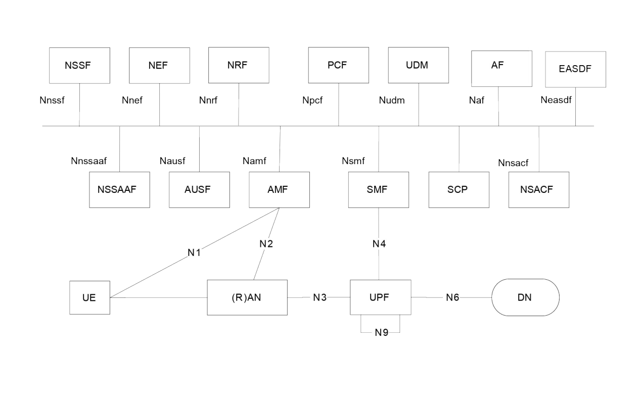
The service-based drawing hangs every control plane function off one horizontal bar. The bar is not a bus and not a cable. It means: each of these functions offers services, and any authorized function may call them. User plane links are still drawn as lines, because those are real links.
The reference point drawing shows the same network as a graph, with a labelled edge — N7, N11, N15 — between each pair that talks. It is easier to follow when you are tracing one procedure.
Which of the two is binding is settled in one sentence: control plane functions in the core shall only use service-based interfaces for their interactions §4.2.1. The graph is a view of the services, not a second way of building the network.
1.5 What this document deliberately does not hold
The architecture clause hands whole areas to other documents, and knowing which saves an afternoon §4.2.1:
| Area | Where it really lives |
|---|---|
| The radio network | TS 38.300, TS 38.401 |
| Security | TS 33.501 |
| Charging | TS 32.240 |
| Procedures and flows | TS 23.502 |
| Policy and charging control | TS 23.503 |
The list of network functions in §4.2.2 is long — around thirty names, plus two things the clause calls network entities rather than functions. What each one does is Who does what in the core, and how they call each other is How one function calls another.
1.6 Where to look next
The scope and the reference list are §1 and §2; the definitions and abbreviations that the rest of the document assumes are §3.1 and §3.2. The full set of architecture drawings, including the ones for roaming, is §4.2.3 and §4.2.4.
The in-depth course of this track works through the architecture clause by clause, including the extra views that each feature adds to the picture.
Check yourself
Answers appear when you pick one, with where they come from.
Q1.1 Which stage of a 3GPP specification is TS 23.501?
The first line of the scope says the document defines the Stage 2 system architecture for the 5G System. Message formats are stage 3 and live elsewhere. §1
Q1.2 A colleague says "the service bus in figure 4.2.3-1". What is wrong with that?
The service-based drawing shows every control plane function offering services on one line. There is no shared bus underneath it, only calls from one function to another. §4.2.1
Q1.3 The 5G core is drawn twice, once with a horizontal bar and once as a graph of labelled links. What is the relationship between the two?
Clause 4.2.1 says control plane functions shall only use service-based interfaces. The reference point drawing labels those same conversations, so it is a view, not an alternative. §4.2.1
Q1.4 Where does the packet a phone sends actually get out of the mobile network?
The user plane stack shows the payload tunnelled from the radio node to a UPF over N3, and the UPF is the point of interconnect to the Data Network. §8.3.1
Q1.5 Which two documents does the scope name as companions to TS 23.501?
The scope names TS 23.502 for the stage 2 procedures and flows, and TS 23.503 for the stage 2 policy control and charging architecture. §1
This chapter was written against TS 23.501 version 20.2.0, verified 2026-08-04. A newer version of the document may say something else.