3GPP 23.501 v20.2.0 — the document's own text
5.6.4.2 Usage of an UL Classifier for a PDU Session
Taught in 12. The connection to a data network (The 5G system architecture, in depth), 5. The connection, and what is promised on it (The 5G system architecture, overview).
In the case of PDU Sessions of type IPv4 or IPv6 or IPv4v6 or Ethernet, the SMF may decide to insert in the data path of a PDU Session an "UL CL" (Uplink classifier). The UL CL is a functionality supported by an UPF that aims at diverting (locally) some traffic matching traffic filters provided by the SMF. The insertion and removal of an UL CL is decided by the SMF and controlled by the SMF using generic N4 and UPF capabilities. The SMF may decide to insert in the data path of a PDU Session a UPF supporting the UL CL functionality during or after the PDU Session Establishment, or to remove from the data path of a PDU Session a UPF supporting the UL CL functionality after the PDU Session Establishment. The SMF may include more than one UPF supporting the UL CL functionality in the data path of a PDU Session.
The UE is unaware of the traffic diversion by the UL CL and does not involve in both the insertion and the removal of UL CL. In the case of a PDU Session of IPv4 or IPv6 or IPv4v6 type, the UE associates the PDU Session with either a single IPv4 address or a single IPv6 Prefix or both of them allocated by the network.
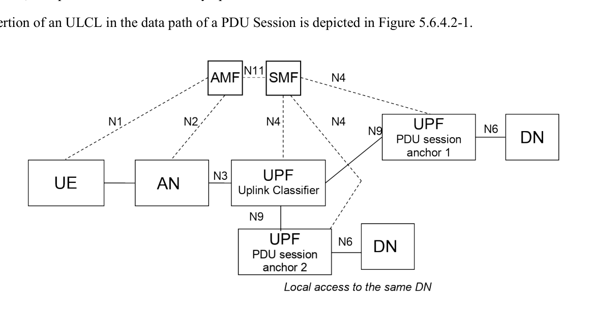
When an UL CL functionality has been inserted in the data path of a PDU Session, there are multiple PDU Session Anchors for this PDU Session. These PDU Session Anchors provide different access to the same DN. In the case of a PDU Session of IPv4 or IPv6 or IPv4v6 type, only one IPv4 address and/or IPv6 prefix is provided to the UE. The SMF may be configured with local policies for some (DNN, S-NSSAI) combinations to release the PDU Session when there is a PSA associated with the IPv4 address allocated to the UE and this PSA has been removed.
NOTE 0: The use of only one IPv4 address and/or IPv6 prefix with multiple PDU Session Anchors assumes that when needed, appropriate mechanisms are in place to correctly forward packets on the N6 reference point. The mechanisms for packet forwarding on the N6 reference point between the PDU Session Anchor providing local access and the DN are outside the scope of this specification.
The UL CL provides forwarding of UL traffic towards different PDU Session Anchors and merge of DL traffic to the UE i.e. merging the traffic from the different PDU Session Anchors on the link towards the UE. This is based on traffic detection and traffic forwarding rules provided by the SMF.
The UL CL applies filtering rules (e.g. to examine the destination IP address/Prefix of UL IP packets sent by the UE) and determines how the packet should be routed. The UPF supporting an UL CL may also be controlled by the SMF to support traffic measurement for charging, traffic replication for LI and bit rate enforcement (Session-AMBR per PDU Session).
NOTE 1: When N9 forwarding tunnel exists between source ULCL and target ULCL, the Session-AMBR per PDU Session can be enforced by the source UL CL UPF.
NOTE 2: The UPF supporting an UL CL may also support a PDU Session Anchor for connectivity to the local access to the data network (including e.g. support of tunnelling or NAT on N6). This is controlled by the SMF.
Additional UL CLs (and thus additional PDU Session Anchors) can be inserted in the data path of a PDU Session to create new data paths for the same PDU Session. The way to organize the data path of all UL CLs in a PDU Session is up to operator configuration and SMF logic and there is only one UPF supporting UL CL connecting to the (R)AN via N3 interface, except when session continuity upon UL CL relocation is used.
The insertion of an ULCL in the data path of a PDU Session is depicted in Figure 5.6.4.2-1.
NOTE 3: It is possible for a given UPF to support both the UL CL and the PDU Session Anchor functionalities.
Due to UE mobility the network may need to relocate the UPF acting as UL CL and establish a new PSA for local access to the DN. To support session continuity during UL CL relocation the network may establish a temporary N9 forwarding tunnel between the source UL CL and target UL CL. The AF may influence the creation of the N9 forwarding tunnel as described in clause 5.6.7.1.
The N9 forwarding tunnel is maintained until:
- all active traffic flowing on it ceases to exist for:
- a configurable period of time; or
- a period of time indicated by the AF;
- until the AF informs the SMF that it can release the source PSA providing local access to the DN.
During the existence of the N9 forwarding tunnel the UPF acting as target UL CL is configured with packet filters that:
- force uplink traffic from existing data sessions between UE and the application in the source local part of the DN (as defined in TS 23.548 [130]) into the N9 forwarding tunnel towards the source UL CL.
- force any traffic related to the application in the target local part of the DN to go to the new local part of the DN via the target PSA.
SMF may send a Late Notification to AF to inform it about the DNAI change as described in clause 4.3.6.3 of TS 23.502 [3]. This notification can be used by the AF e.g. to trigger mechanisms in the source local part of the DN to redirect the ongoing traffic sessions towards an application in the target local part of the DN. SMF can also send late notification to the target AF instance if associated with this target local part of the DN.
The procedure for session continuity upon UL CL relocation is described in clause 4.3.5.7 of TS 23.502 [3].
When an I-SMF is inserted for a PDU Session, the details of UL CL insertion which is controlled by an I-SMF is described in clause 5.34.4.