3GPP 38.300 v19.3.0 — the document's own text
16.12.2.1 L2 UE-to-Network Relay
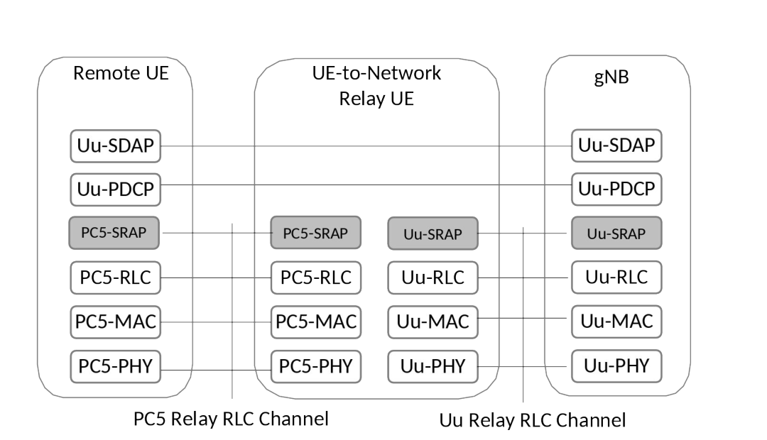
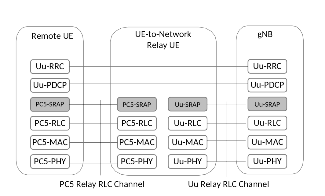
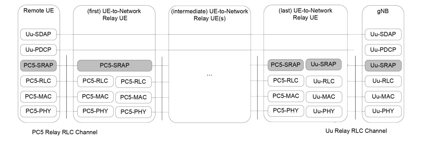
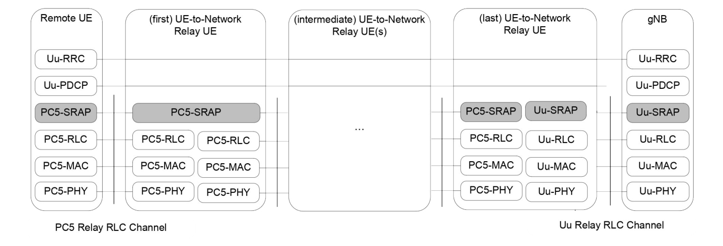
The protocol stacks for the user plane and control plane of single-hop L2 U2N Relay architecture are illustrated in Figure 16.12.2.1-1 and Figure 16.12.2.1-2. The protocol stacks for the user plane and control plane of multi-hop L2 U2N Relay architecture are illustrated in Figure 16.12.2.1-3 and Figure 16.12.2.1-4. The SRAP sublayer is placed above the RLC sublayer for both CP and UP at both PC5 interface and Uu interface. The Uu SDAP, PDCP and RRC are terminated between L2 U2N Remote UE and gNB, while SRAP, RLC, MAC and PHY are terminated in each hop (i.e., the link between L2 U2N Remote UE and the L2 U2N Relay UE, the link between L2 U2N Relay UEs, and the link between L2 U2N Relay UE and the gNB).
For L2 U2N Relay, the SRAP sublayer over PC5 hop is only for the purpose of bearer mapping. The SRAP sublayer is not present over PC5 hop for relaying the L2 U2N Remote UE's message on BCCH and PCCH. For L2 U2N Remote UE's message on SRB0, the SRAP header is not present over PC5 hop between the U2N Remote UE and the directly connected U2N Relay UE, but the SRAP header is present over Uu hop or PC5 hop between U2N Relay UEs for both DL and UL.
For L2 U2N Relay, for uplink:
- The Uu/PC5 SRAP sublayer at the U2N Relay UE performs UL bearer mapping between end-to-end Uu Radio Bearers of L2 U2N remote UE (identified for the purposes of this mapping by the local Remote UE ID and an associated bearer ID) and egress Uu/PC5 Relay RLC channels over the L2 U2N Relay UE Uu/PC5 interface. For uplink relaying traffic, the different end-to-end Uu Radio Bearers (SRBs or DRBs) of the same L2 U2N Remote UE and/or different L2 U2N Remote UEs can be multiplexed over the same egress Uu/PC5 Relay RLC channel;
- The Uu/PC5 SRAP sublayer at the U2N Relay UE supports L2 U2N Remote UE identification for the UL traffic. The identity information of L2 U2N Remote UE end-to-end Uu Radio Bearer and a local Remote UE ID are included in the Uu SRAP header at UL in order for gNB to correlate the received packets for the specific PDCP entity associated with the right end-to-end Uu Radio Bearer of the L2 U2N Remote UE;
- The PC5 SRAP sublayer at the L2 U2N Remote UE supports UL bearer mapping between L2 U2N Remote UE end-to-end Uu Radio Bearers and egress PC5 Relay RLC channels.
For L2 U2N Relay, for downlink:
- The Uu SRAP sublayer performs DL bearer mapping at gNB to map end-to-end Uu Radio Bearer (SRB, DRB) of L2 U2N Remote UE (identified for the purposes of this mapping by the local Remote UE ID and an associated bearer ID) into Uu Relay RLC channel. The Uu SRAP sublayer performs DL bearer mapping and data multiplexing between multiple end-to-end Radio Bearers (SRBs or DRBs) of a L2 U2N Remote UE and/or different L2 U2N Remote UEs and one Uu Relay RLC channel over the L2 U2N Relay UE Uu interface;
- The Uu/PC5 SRAP sublayer at the U2N Relay UE supports L2 U2N Remote UE identification for DL traffic. The identity information of L2 U2N Remote UE end-to-end Uu Radio Bearer and a local Remote UE ID are included into the Uu SRAP header by the gNB at DL for the L2 U2N Relay UE to identify the corresponding end-to-end Uu Radio Bearer(s) of L2 U2N Remote UE;
- The PC5 SRAP sublayer at the L2 U2N Relay UE performs DL bearer mapping and multiplexing between end-to-end Uu Radio Bearers of L2 U2N remote UE(s) and egress PC5 Relay RLC channels;
- The PC5 SRAP sublayer at the L2 U2N Remote UE correlates the received packets with the right PDCP entity associated with the given end-to-end Uu Radio Bearer of the L2 U2N Remote UE based on the identity information included in the PC5 SRAP header.
A local Remote UE ID is included in both PC5 SRAP header and Uu SRAP header. L2 U2N Relay UE is configured by the gNB with the local Remote UE ID(s) to be used in SRAP header. L2 U2N Remote UE obtains the local Remote ID from the gNB via Uu RRC messages including RRCSetup, RRCReconfiguration, RRCResume and RRCReestablishment.
The end-to-end DRB(s) or end-to-end SRB(s), except SRB0, of L2 U2N Remote UE can be multiplexed to the PC5 Relay RLC channels and Uu Relay RLC channels in both PC5 hop and Uu hop, but an end-to-end DRB and an end-to-end SRB can neither be mapped into the same PC5 Relay RLC channel nor be mapped into the same Uu Relay RLC channel.
It is the gNB responsibility to avoid collision on the usage of local Remote UE ID. The gNB can update the local Remote UE ID by sending the updated local Remote UE ID via RRCReconfiguration message. The serving gNB can perform local Remote UE ID update independent of the PC5 unicast link L2 ID update procedure.