3GPP 38.300 v19.3.0 — the document's own text
Annex G Components of Mobility Latency
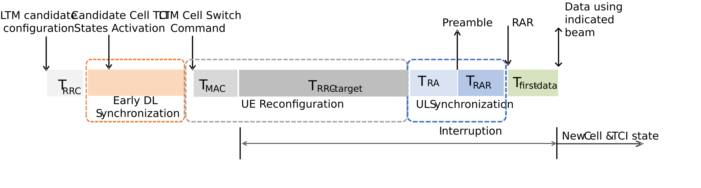
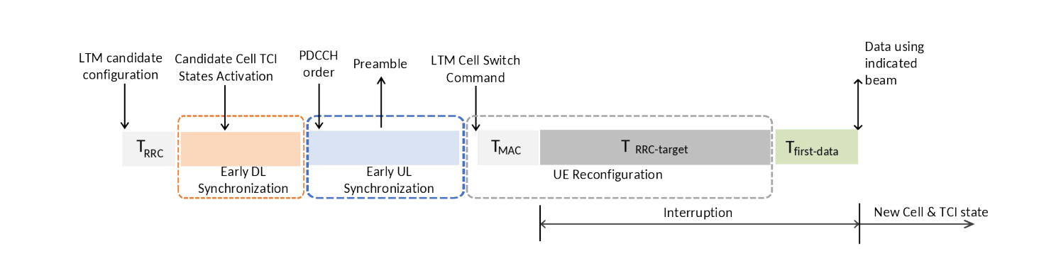
Mobility interruption time for L1/L2 Triggered Mobility (LTM) is the time from UE receives the cell switch command to UE performs the first DL/UL reception/transmission on the indicated beam of the target cell.
The latency of the mobility procedure for LTM is characterized by the terms illustrated in Figure G-1.
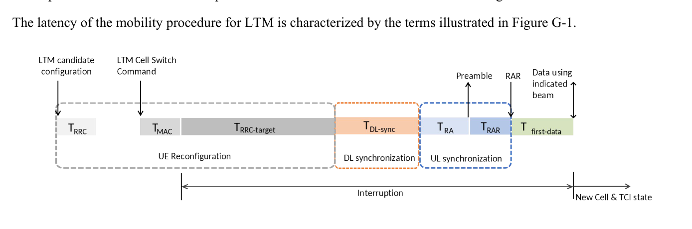
Each component of mobility latency is described in the table below. The value of TRRC is specified in clause 12 of TS 38.331 [12].
Table G-1: Components of Mobility Latency
| Component | Meaning |
|---|---|
| TRRC | Processing time for RRCReconfiguration carrying candidate configurations |
| TMAC | Time for processing the LTM cell switch command MAC CE |
| TRRC-target | Time for processing and applying the target configuration |
| TDL-sync | Time for DL synchronization |
| TRA | Time until RA transmission |
| TRAR | Time until RAR reception |
| Tfirst-data | Time for UE performs the first DL/UL reception/ transmission on the indicated beam of the target cell, after RAR |
The latency of the RACH-based and RACH-less LTM procedure is characterized by the terms illustrated in Figure G-2 and Figure G-3. In particular, Figure G-2 shows the LTM procedure where the UE performs DL synchronization toward an LTM candidate cell before performing an LTM cell switch which involves a random access procedure. Further, Figure G-3 shows the LTM procedure where the UE performs the UL and DL synchronization before performing an LTM cell switch which does not involve a random access procedure. In both figures, it is highlighted how the overall mobility latency of LTM can be reduced by early synchronization procedure. Interruption time requirements (not represented by this annex) are specified in clause 6.3 of TS 38.133[13].