3GPP 38.300 v19.3.0 — the document's own text
9.2.3.5.2 C-Plane Handling
Cell switch command is conveyed in a MAC CE, which contains the necessary information to perform the LTM cell switch.
The overall procedure for intra-gNB LTM is shown in Figure 9.2.3.5.2-1 below. Subsequent LTM is done by repeating the early synchronization, LTM cell switch execution, and LTM cell switch completion steps without the need to release, reconfigure or add other LTM candidate configurations after each LTM cell switch completion. The general procedure over the air interface is applicable to SCG LTM. Further details of SCG LTM can be found in TS 37.340 [21].
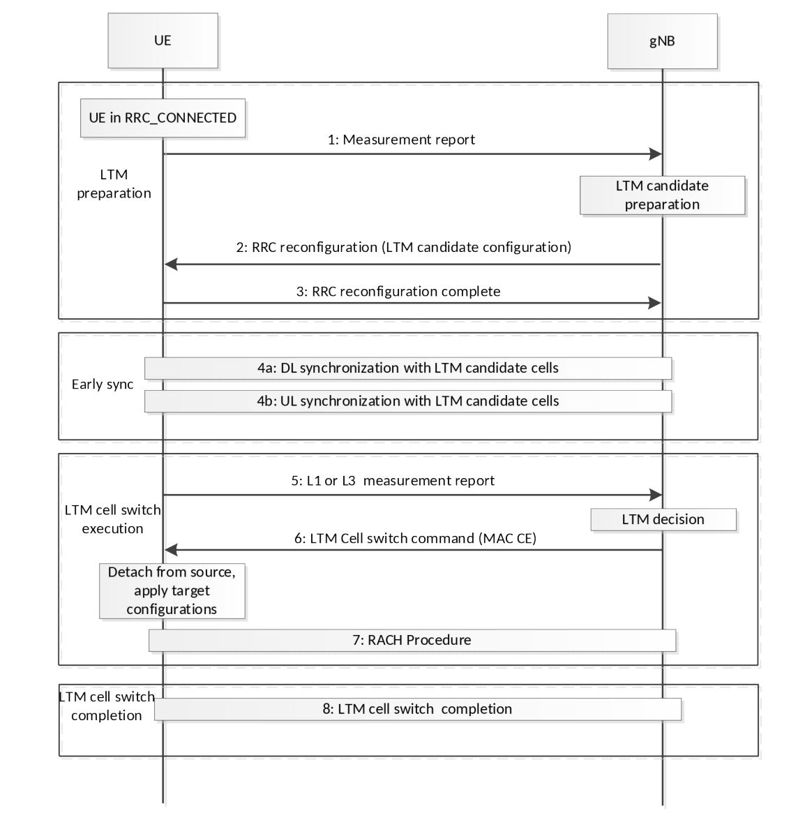
The procedure for intra-gNB LTM is as follows:
1. The UE sends a MeasurementReport message to the gNB. The gNB decides to configure LTM and initiates LTM preparation.
2. The gNB transmits an RRCReconfiguration message to the UE including the LTM candidate configurations.
3. The UE stores the LTM candidate configurations and transmits an RRCReconfigurationComplete message to the gNB.
4a. The UE performs DL synchronization with the LTM candidate cell(s) before receiving the cell switch command. The UE may activate and deactivate TCI states of LTM candidate cell(s), as triggered by the gNB and defined in TS 38.133 [13].
4b. The UE may perform UL synchronization with LTM candidate cell(s) before receiving the cell switch command, by using UE-based TA measurement, if configured, and/or by transmitting a preamble towards the candidate cell, as triggered by the gNB. When UE-based TA measurement is configured, UE acquires the TA value(s) of the candidate cell(s) by measurement. UE performs early TA acquisition with the candidate cell(s) as requested by the network before receiving the cell switch command as specified in clause 9.2.6 and TS 38.133 [13]. This is done via CFRA triggered by a PDCCH order from the source cell, following which the UE sends preamble towards the indicated candidate cell. In order to minimize the data interruption of the source cell due to CFRA towards the candidate cell(s), the UE does not receive random access response from the network for the purpose of TA value acquisition and the TA value of the candidate cell is indicated in the cell switch command. The UE does not maintain the TA timer for the candidate cell and relies on network implementation to guarantee the TA validity.
5. The UE performs L1 measurements on the configured LTM candidate cell(s) and transmits L1 measurement reports to the gNB. L1 measurement should be performed as long as RRC reconfiguration (step 2) is applicable. The UE can also perform L3 measurement reporting to the gNB, including beam level measurement results on cell(s) which are configured as LTM candidate cell(s) according to the received network configuration.
6. The gNB decides to execute cell switch to a target cell and transmits an LTM cell switch command MAC CE triggering cell switch by including a target configuration ID which indicates the index of the candidate configuration of the target cell, a beam indicated with a TCI state or beams indicated with DL and UL TCI states, and a timing advance command for the target cell, if available. The UE switches to the target cell and applies the candidate configuration indicated by the target configuration ID.
7. The UE performs the random access procedure towards the target cell, if UE does not have valid TA of the target cell as specified in clause 5.18.35 of TS 38.321[6].
8. The UE completes the LTM cell switch procedure by sending RRCReconfigurationComplete message to target cell. If the UE has performed a RA procedure in step 7 the UE considers that LTM cell switch execution is successfully completed when the random access procedure is successfully completed. For RACH-less LTM, the UE considers that LTM cell switch execution is successfully completed when the UE determines that the network has successfully received its first UL data.
The steps 4-8 can be performed multiple times for subsequent LTM cell switch executions using the LTM candidate configuration(s) provided in step 2.
The overall procedure for inter-gNB LTM is shown in Figure 9.2.3.5.2-2 below.
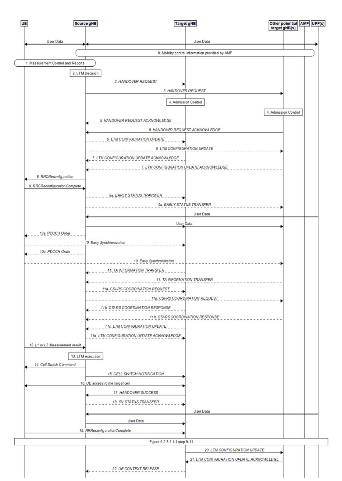
The procedure for inter-gNB LTM is as follows:
1. The UE sends a MeasurementReport message (L3 measurement result) to the source gNB containing measurements of neighbouring cells.
2. The source gNB decides to configure LTM.
3. The source gNB requests LTM for one or more candidate cells belonging to the source gNB and/or one or more candidate gNB(s). For inter-gNB LTM, the source gNB initiates a HANDOVER REQUEST message per candidate cell containing one candidate cell ID and may contain the CSI resource configuration for subsequent LTM. For both intra and inter-gNB LTM, the source gNB may request the candidate cell(s)/gNB(s) to provide the CSI-RS resource configuration for L1 RSRP measurement. The source gNB may include the proposed LTM no security change related information, the proposed L2 reset configuration information, and the proposed UE-based TA measurement configuration information. For inter-gNB LTM, the source gNB includes the same source NG-RAN node UE XnAP ID for all the HANDOVER REQUEST messages to one candidate gNB.
NOTE 0a: When providing the LTM no security change, L2 reset, and UE-based TA measurement ID lists, it is up to source gNB implementation to ensure that the number of IDs in each list is sufficient for the candidate gNB to assign for the candidate cell(s) requested to the candidate gNB.
NOTE 0b: In the case of multiple candidate gNBs, the source gNB provides distinct ID values to each candidate gNB for the proposed LTM no security change related information and L2 reset configuration information.
4. Admission Control may be performed by the candidate cells(s)/gNB(s).
5. The candidate gNB(s) prepares and provides the LTM configuration(s) to the source gNB. For inter-gNB LTM, the candidate gNB(s) respond(s) with HANDOVER REQUEST ACKNOWLEDGE message to the source gNB including the generated RRC configurations for the accepted candidate cell. For both intra and inter-gNB LTM, the candidate gNB(s) may include the CSI-RS resource configuration for early CSI acquisition, and upon request, may also include additional information related to the CSI-RS resource configuration for L1 measurement and early sync information. The candidate gNB(s) also responds with the selected LTM no security change related information. For inter-gNB LTM, each candidate gNB includes the same target NG-RAN node UE XnAP ID for all the HANDOVER REQUEST ACKNOWLEDGE messages it responds. The candidate gNB may respond the selected L2 reset configuration information and/or the selected UE-based TA measurement configuration information upon request.
6. The source gNB sends an LTM CONFIGURATION UPDATE message to the candidate gNB(s) to update the LTM configurations of candidate cell(s). The source gNB may include the common CSI resource configuration, the LTM configuration ID mapping list and the LTM security information.
7. The candidate gNB(s) sends the LTM CONFIGURATION UPDATE ACKNOWLEDGE message to the source gNB. The candidate gNB(s) may provide the CSI report configuration. The candidate gNB may also include the CSI report configuration for early CSI acquisition of the candidate cell(s).
NOTE 1: Step 6 may also be triggered after step 14, or after step 17 by implementation for subsequent LTM.
NOTE 2: Step 6 and Step 7 are triggered if early CSI acquisition is applied.
8. The source gNB sends an RRCReconfiguration message to the UE.
9. The UE stores the LTM candidate configurations and sends an RRCReconfigurationComplete message to the source gNB.
NOTE 3: Void.
9a. If early data forwarding is applied, the source gNB sends the EARLY STATUS TRANSFER message to the candidate gNB(s).
10/11. Early DL and UL synchronization to some LTM candidate cell(s) may be performed. The source gNB may activate or deactivate the TCI states of the candidate LTM cells. Depending on network configuration, the UE may perform early UL synchronization with LTM candidate cell(s), by using UE-based TA measurement, if configured, and/or by transmitting a preamble towards the candidate cell, as triggered by the source gNB. With a network triggered UL synchronization, a PDCCH order is received from the source cell to trigger CFRA to a candidate cell, the UE performs early TA acquisition by sending preamble towards the indicated candidate cell. In order to minimize the data interruption on the source cell due to CFRA towards the indicated candidate cell(s), the UE does not receive random access response from the network for the purpose of TA value acquisition. The candidate gNB(s) sends the TA INFORMATION TRANSFER message to the source gNB instead.
11a/11b. The source gNB may initiate a CSI-RS COORDINATION REQUEST message to request the candidate gNB(s) to activate or deactivate semi-persistent CSI-RS resources for Layer 1 measurements and/or for early CSI acquisition. The candidate gNB(s) respond to the source gNB with the CSI-RS COORDINATION RESPONSE message indicating whether the requested CSI-RS resources are activated or deactivated.
NOTE 3a: Step 11a/11b may be triggered by implementation after step 9.
NOTE 3b: The Handover Cancel procedure may be initiated either before or after the cell switch by the serving gNB.
11c/11d. The candidate gNB may initiate an LTM CONFIGURATION UPDATE message to inform the source gNB about the update of LTM configurations for one or more candidate cells belonging to the candidate gNB. The source gNB responds with the LTM CONFIGURATION UPDATE ACKNOWLEDGE message to confirm the update.
NOTE 3c: The source gNB may further initiate another LTM Configuration Update procedure(s) with the candidate gNB(s) to coordinate the updated LTM configurations. If required, the source gNB may reconfigure the UE with the latest LTM configuration.
12. The UE performs L1 or L3 measurements on the configured LTM candidate cell(s) and transmits L1 or L3 measurement reports to the source gNB, if configured. L1 or L3 measurement should be performed as long as RRC reconfiguration (step 8) is applicable.
13. The source gNB determines to initiate LTM. L3 measurement can also be used to determine this step.
14. The source gNB decides to execute cell switch to a target cell and transmits an LTM cell switch command MAC CE triggering cell switch by including a target configuration ID which indicates the index of the candidate configuration, a beam indicated with a TCI state or beams indicated with DL and UL TCI states, and a TA command for the target cell. In case of a security context change, the LTM cell switch command MAC CE also contains the NCC value. The UE switches to the target cell and applies the candidate configuration indicated by the target configuration ID. In case of security context change, the UE generates and applies the new security keys based on the received NCC value.
NOTE 4: Up to implementation, data forwarding and SN Status Transfer may be initiated once the source gNB triggers the inter-gNB LTM cell switch for the UE in Step 14.
15. The source gNB sends the CELL SWITCH NOTIFICATION message to the target gNB to indicate the initiation of Cell Switch command to the UE. The source gNB may inform the acquired TA related information.
NOTE 4a: The order in which step 14 and step 15 are executed is up to implementation.
16. The UE performs the random access procedure towards the target cell, if UE does not have valid TA of the target cell as specified in clause 5.18.35 of TS 38.321[6].
17/18. The target gNB sends the HANDOVER SUCCESS message to the source gNB to inform that the UE has successfully accessed the target cell. In return, the source gNB sends the SN STATUS TRANSFER message following the principles described in step 7 of Intra-AMF/UPF Handover in clause 9.2.3.2.1.
NOTE 5: Late data forwarding may be initiated as soon as the source gNB receives the HANDOVER SUCCESS message.
NOTE 6: The source gNB may initiate the CSI-RS Coordination procedure to deactivate the semi-persistent CSI-RS resource(s) of candidate cell(s) on the candidate gNB(s) after the UE successfully accesses the target cell.
19. The UE completes the LTM cell switch procedure by sending RRCReconfigurationComplete message to target cell. If the UE has performed a RA procedure in step 16 the UE considers that LTM cell switch execution is successfully completed when the random access procedure is successfully completed. For RACH-less LTM, the UE considers that LTM cell switch execution is successfully completed when the UE determines that the network has successfully received its first UL data
NOTE 7: Steps 17/18 and 19 do not have to occur one after the other. The target gNB may send the HANDOVER SUCCESS message to the source gNB after receiving the RRCReconfigurationComplete message.
20. The new source gNB (i.e., the target gNB) sends the LTM CONFIGURATION UPDATE message to the candidate gNBs. This message includes the new security key(s) to be used with the UE.
21. The candidate gNB(s) responds with the LTM CONFIGURATION UPDATE ACKNOWLEDGE message to the new source gNB.
22. The new source gNB may send the UE CONTEXT RELEASE message to inform the old source gNB to release radio and C-plane related resources associated to the UE context if no LTM candidate cell(s) exist in the old source gNB. Any ongoing data forwarding may continue.
The steps 9a-22 can be performed multiple times for subsequent LTM cell switch executions using the LTM candidate configuration(s) provided in step 8.
The procedure over the air interface described in Figure 9.2.3.5.2-1 is applicable to both intra-gNB LTM and inter-gNB LTM. The overall LTM procedures over F1-C interface are captured in TS 38.401[4].