3GPP 38.300 v19.3.0 — the document's own text
5.2.4 Synchronization signal and PBCH block
Taught in 2. The six working groups and the line between them (TSG RAN — the group that specifies the radio, overview), 2. The six groups, and what each one worries about (TSG RAN — the group that specifies the radio, quick start).
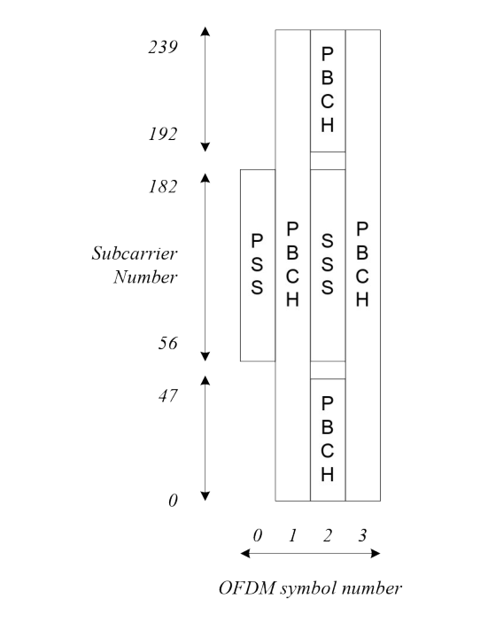
The Synchronization Signal and PBCH block (SSB) consists of primary and secondary synchronization signals (PSS, SSS), each occupying 1 symbol and 127 subcarriers, and PBCH spanning across 3 OFDM symbols and 240 subcarriers, but on one symbol leaving an unused part in the middle for SSS as show in Figure 5.2.4-1. For the 3 MHz channel bandwidth, the PBCH is further equally punctured from both edges to span 144 subcarriers. The possible time locations of SSBs within a half-frame are determined by sub-carrier spacing and the periodicity of the half-frames where SSBs are transmitted is configured by the network. During a half-frame, different SSBs may be transmitted in different spatial directions (i.e. using different beams, spanning the coverage area of a cell).
Within the frequency span of a carrier, multiple SSBs can be transmitted. The PCIs of SSBs transmitted in different frequency locations do not have to be unique, i.e. different SSBs in the frequency domain can have different PCIs. However, when an SSB is associated with an RMSI, the SSB is referred to as a Cell-Defining SSB (CD-SSB). A PCell is always associated to a CD-SSB located on the synchronization raster.
When an SSB is not associated with an RMSI, the SSB is referred to as a non-Cell Defining SSB (NCD-SSB), which can be used to perform RLM, BFD, and RRM measurements and measurements for RA resource selection inside the active DL BWP when the active BWP does not contain the CD-SSB. A UE may be configured with multiple SSBs provided that each BWP is configured with at most one SSB (CD-SSB or NCD-SSB).
Polar coding is used for PBCH.
The UE may assume a band-specific sub-carrier spacing for the SSB unless a network has configured the UE to assume a different sub-carrier spacing.
PBCH symbols carry its own frequency-multiplexed DMRS.
QPSK modulation is used for PBCH.
The PBCH physical layer model is described in TS 38.202 [20].