3GPP 38.300 v19.3.0 — the document's own text
16.9.2.1 Overview
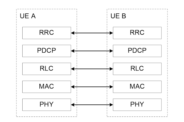
The AS protocol stack for the control plane for SCCH for RRC in the PC5 interface consists of RRC, PDCP, RLC and MAC sublayers, and the physical layer. The protocol stack of control plane for SCCH for RRC is shown in Figure 16.9.2.1-1.
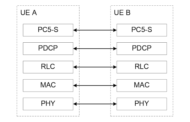
For support of PC5-S protocol specified in TS 23.287 [40], PC5-S is located on top of PDCP, RLC and MAC sublayers, and the physical layer in the control plane protocol stack for SCCH for PC5-S, as shown in Figure 16.9.2.1-2.
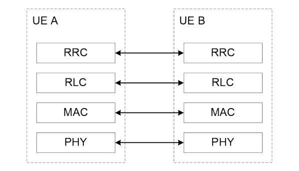
The AS protocol stack for SBCCH in the PC5 interface consists of RRC, RLC, MAC sublayers, and the physical layer as shown below in Figure 16.9.2.1-3.
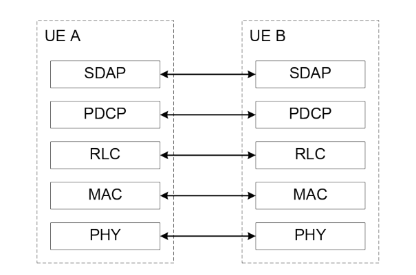
The AS protocol stack for user plane in the PC5 interface consists of SDAP, PDCP, RLC and MAC sublayers, and the physical layer. The protocol stack of user plane is shown in Figure 16.9.2.1-4.
Sidelink Radio bearers (SLRB) are categorized into two groups: sidelink data radio bearers (SL DRB) for user plane data and sidelink signalling radio bearers (SL SRB) for control plane data. Separate SL SRBs using different SCCHs are configured for PC5-RRC and PC5-S signalling respectively.