3GPP 38.300 v19.3.0 — the document's own text
16.12.6.2 Switching from direct to indirect path
The gNB can select a L2 U2N Relay UE in any RRC state i.e., RRC_IDLE, RRC_INACTIVE, or RRC_CONNECTED, as a target L2 U2N Relay UE for switching from a direct path to an indirect path if the target path is a single-hop. If the target path is a multi-hop, the gNB selects L2 U2N Relay UE in RRC_CONNECTED as a target first L2 U2N Relay UE.
For service continuity of L2 U2N Remote UE, the following procedure is used, in case of the L2 U2N Remote UE switching from direct to indirect path under the same gNB via a L2 U2N Relay UE in RRC_CONNECTED:
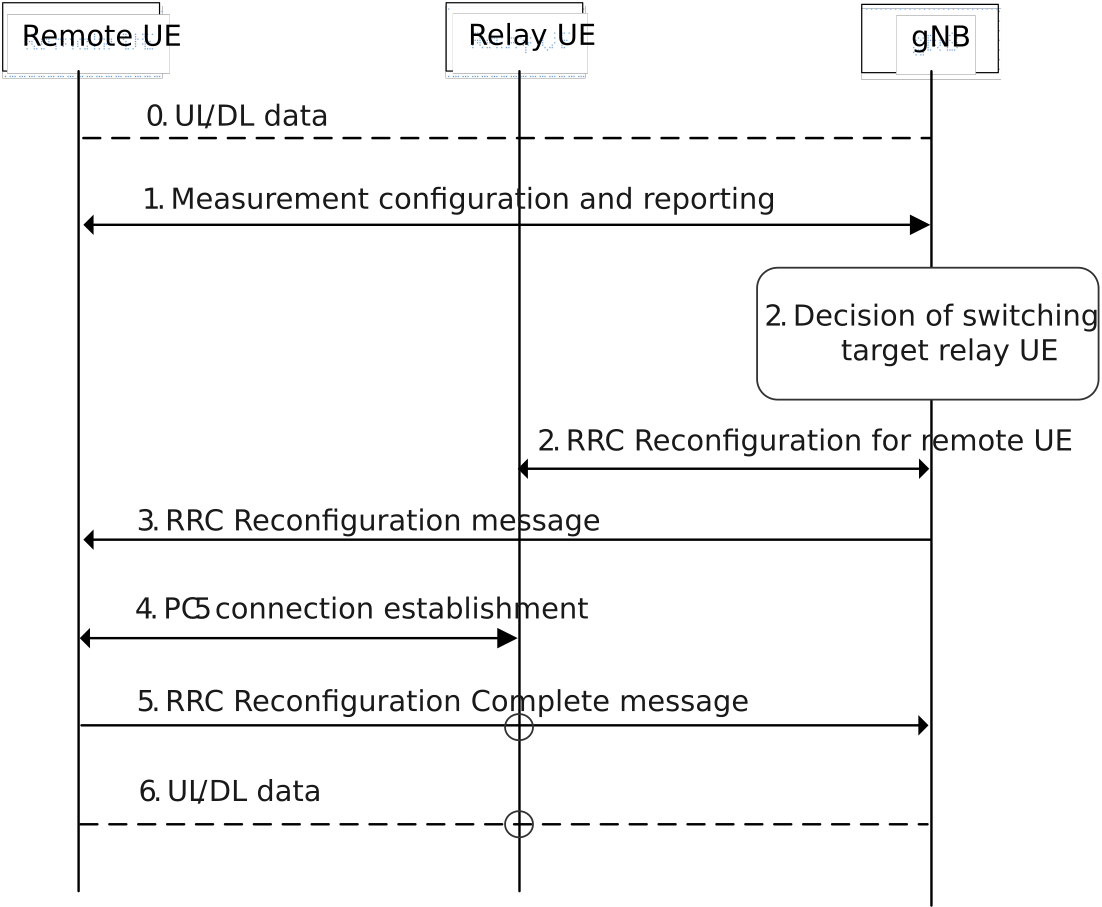
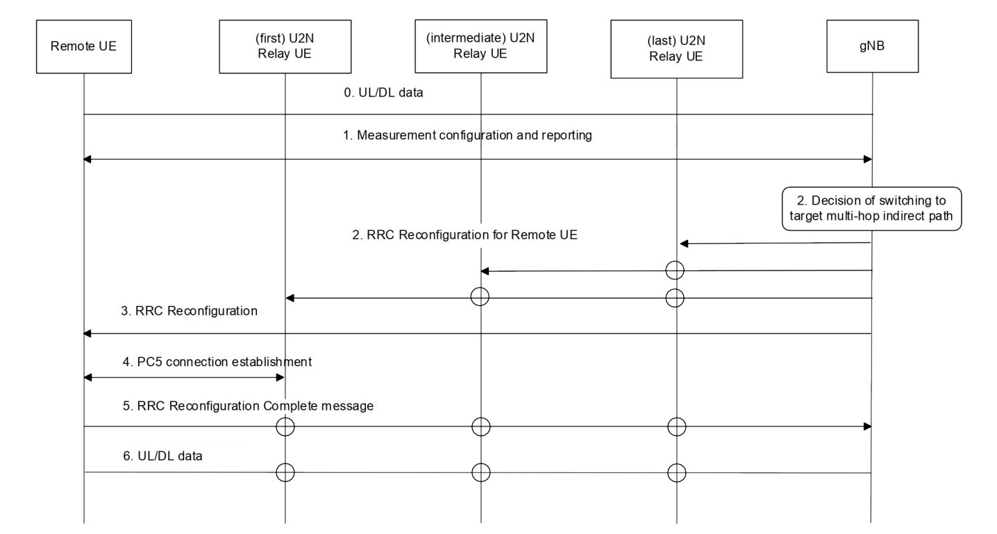
1. The L2 U2N Remote UE reports one or multiple candidate L2 U2N Relay UE(s) and Uu measurements, after it measures/discovers the candidate L2 U2N Relay UE(s):
- The L2 U2N Remote UE filters the appropriate L2 U2N Relay UE(s) according to relay selection criteria before reporting. The L2 U2N Remote UE shall report only the L2 U2N Relay UE candidate(s) that fulfil the higher layer criteria;
- The reporting includes at least a L2 U2N Relay UE ID, a L2 U2N Relay UE's serving cell ID, and a sidelink measurement quantity information. SD-RSRP is used as sidelink measurement quantity.
2. The gNB decides to switch the L2 U2N Remote UE to a target L2 U2N Relay UE for the single-hop case or to a target path with multiple L2 U2N Relay UEs for the multi-hop case. The gNB sends an RRCReconfiguration message to the target L2 U2N Relay UE, which includes at least the L2 U2N Remote UE's local ID and L2 ID, Uu Relay RLC channel and PC5 Relay RLC channel configuration for relaying, and bearer mapping configuration for the single-hop case. For the multi-hop case, the gNB sends the RRCReconfiguration messages to the target L2 U2N multi-hop relay UEs including the last U2N relay UE, the intermediate U2N relay UE and the first U2N relay UE on the target path to reconfigure the connection for Remote UE.
3. The gNB sends the RRCReconfiguration message to the L2 U2N Remote UE. The RRCReconfiguration message includes at least the L2 U2N Relay UE ID for the single-hop case or the L2 First U2N Relay UE ID on the target path for the multi-hop case, Remote UE's local ID, PC5 Relay RLC channel configuration for relay traffic and the associated end-to-end Uu radio bearer(s). The L2 U2N Remote UE stops User Plane and Control Plane transmission over the direct path after reception of the RRCReconfiguration message from the gNB.
4. The L2 U2N Remote UE establishes PC5-RRC connection with target L2 U2N Relay UE for the single-hop case or with the L2 First U2N Relay UE on the target path for the multi-hop case.
5. The L2 U2N Remote UE completes the path switch procedure by sending the RRCReconfigurationComplete message to the gNB via the L2 U2N Relay UE for the single-hop case or via L2 First U2N Relay UE for the multi-hop case.
6. The data path is switched from direct path to indirect path between the L2 U2N Remote UE and the gNB.
For service continuity of L2 U2N Remote UE, the following procedure is used, in case of the L2 U2N Remote UE switching from direct to indirect path via a L2 U2N Relay UE in RRC_CONNECTED under another gNB:
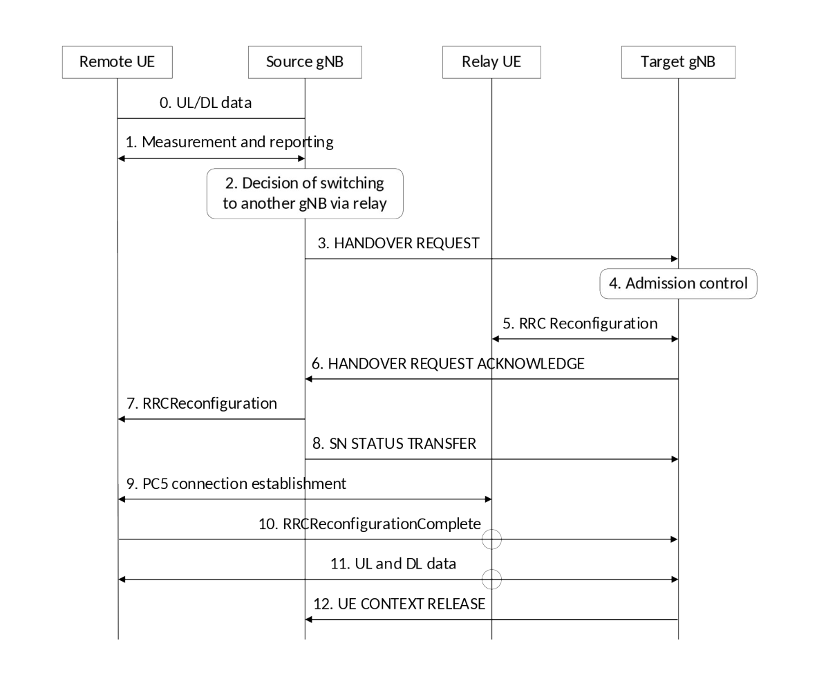
1. The L2 U2N Remote UE reports one or multiple candidate L2 U2N Relay UE(s) and Uu measurements to the source gNB, after it measures/discovers the candidate L2 U2N Relay UE(s):
- The L2 U2N Remote UE filters the appropriate L2 U2N Relay UE(s) according to relay selection criteria before reporting. The L2 U2N Remote UE shall report only the L2 U2N Relay UE candidate(s) that fulfil the higher layer criteria;
- The reporting includes at least a L2 U2N Relay UE ID, a L2 U2N Relay UE's serving cell ID, and a sidelink measurement quantity information. SD-RSRP is used as sidelink measurement quantity.
2. The source gNB decides to trigger path switch for the L2 U2N Remote UE onto indirect path of the target gNB, based on MeasurementReport and RRM information.
3. The source gNB sends a HANDOVER REQUEST message to the target gNB to prepare the path switch at the target side. The HANDOVER REQUEST message includes Remote UE L2 ID and a list of candidate target Relay UE IDs belonging to one cell of the target gNB.
4. Admission Control may be performed by the target gNB.
5. The target gNB selects one target Relay UE from the list of candidate Relay UEs provided by the source gNB, and sends the RRCReconfiguration message to L2 U2N Relay UE for relaying configuration, which includes at least the L2 U2N Remote UE's local ID and L2 ID, Uu Relay RLC channel and PC5 Relay RLC channel configuration for relaying, and bearer mapping configuration. If the target gNB fails to select a target Relay UE from the list of candidate Relay UEs, the target gNB rejects the handover request from the source gNB.
6. The target gNB sends the HANDOVER REQUEST ACKNOWLEDGE message to the source gNB, which contains RRC configuration for L2 U2N Remote UE at the target side.
7. The source gNB sends the RRCReconfiguration message to the L2 U2N Remote UE, which includes at least the L2 U2N Relay UE ID, Remote UE's local ID, PC5 Relay RLC channel configuration for relay traffic and the associated Uu end-to-end radio bearer(s). The L2 U2N Remote UE stops User Plane and Control Plane transmission over the direct path after reception of the RRCReconfiguration message from the source gNB.
8. The source gNB sends the SN STATUS TRANSFER message to the target gNB to convey the uplink PDCP SN receiver status and the downlink PDCP SN transmitter status of the L2 U2N Remote UE's DRBs for which PDCP status preservation applies (i.e. for RLC AM).
9. The L2 U2N Remote UE establishes PC5 connection with L2 U2N Relay UE.
10. The L2 U2N Remote UE sends the RRCReconfigurationComplete message to target gNB via the L2 U2N Relay UE.
11. The data path is switched from direct path to indirect path between the L2 U2N Remote UE and the target gNB via the target L2 U2N Relay UE.
12. The target gNB sends the UE CONTEXT RELEASE message to inform the source gNB about the success of the path switch.
In case the selected L2 U2N Relay UE for direct to single-hop indirect path switch is in RRC_IDLE or RRC_INACTIVE, after receiving the path switch command, the L2 U2N Remote UE establishes a PC5 link with the L2 U2N Relay UE and sends the RRCReconfigurationComplete message via the L2 U2N Relay UE, which triggers the L2 U2N Relay UE to enter RRC_CONNECTED state. The procedure for L2 U2N Remote UE switching to single-hop indirect path in Figure 16.12.6.2-1a can be also applied for the case that the selected L2 U2N Relay UE for direct to single-hop indirect path switch is in RRC_IDLE or RRC_INACTIVE with the exception that the RRCReconfiguration message is sent from the gNB to the L2 U2N Relay UE after the L2 U2N Relay UE enters RRC_CONNECTED state, which happens during step 5 in Figure 16.12.6.2-1a, and during step 10 in Figure 16.12.6.2-2.