3GPP 38.300 v19.3.0 — the document's own text
16.10.3 Protocol Architecture
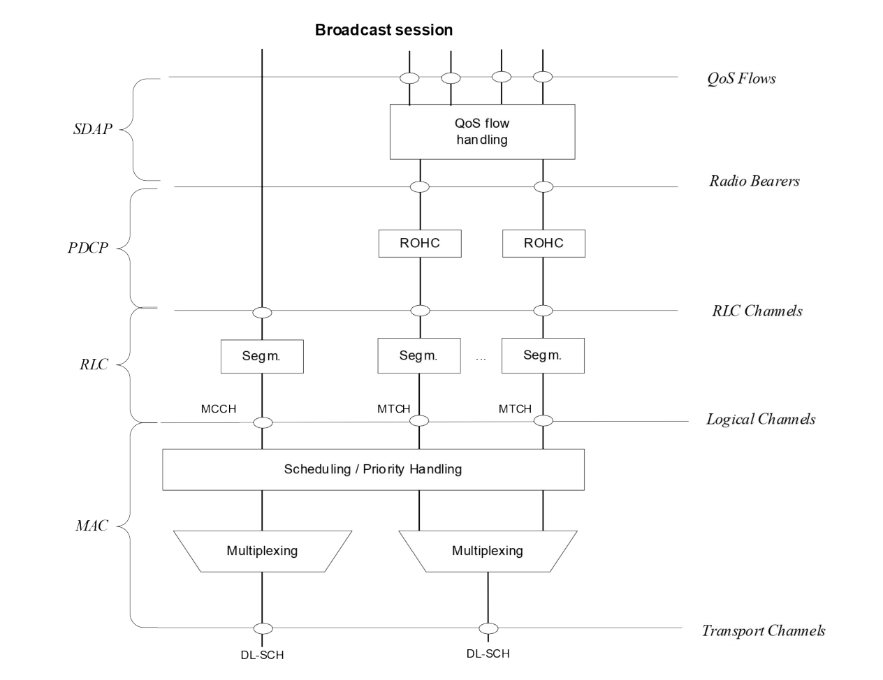
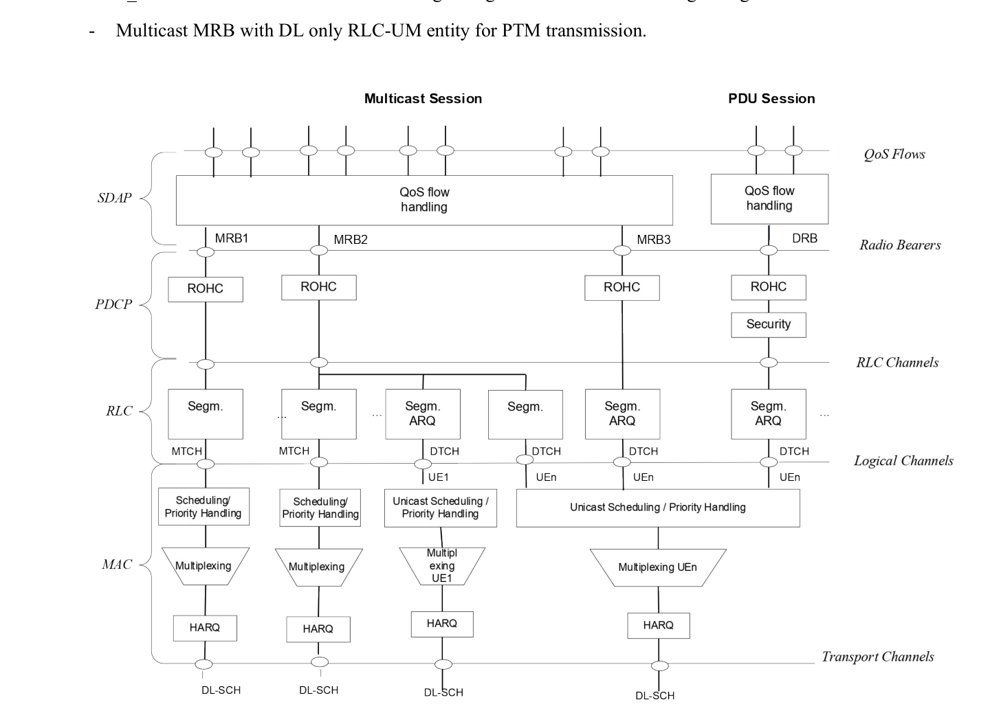
Figures 16.10.3-1 and 16.10.3-2 depict the downlink Layer 2 architecture for multicast session and broadcast session respectively, where MBS protocol stack comprises the same layer 2 sublayers as described in clause 6 with the following differences:
- SDAP sublayer provides only the following functionalities:
- Mapping between an MBS QoS flow and an MRB;
- Transfer of user plane data.
- PDCP sublayer provides only the following functionalities:
- Transfer of user plane data;
- Maintenance of PDCP SNs;
- Header compression and decompression using the ROHC protocol or EHC protocol;
- Reordering and in-order delivery;
- Duplicate discarding.
- For a multicast session, gNB provides one or more of the following multicast MRB configuration(s) to the UE in RRC_CONNECTED state via dedicated RRC signalling:
- Multicast MRB with DL only RLC-UM or bidirectional RLC-UM configuration for PTP transmission;
- Multicast MRB with RLC-AM entity configuration for PTP transmission;
- Multicast MRB with DL only RLC-UM entity for PTM transmission;
- Multicast MRB with two RLC-UM entities, one DL only RLC-UM entity for PTP transmission and the other DL only RLC-UM entity for PTM transmission;
- Multicast MRB with three RLC-UM entities, one DL RLC-UM entity and one UL RLC-UM entity for PTP transmission and the other DL only RLC-UM entity for PTM transmission;
- Multicast MRB with two RLC entities, one RLC-AM entity for PTP transmission and the other DL only RLC-UM entity for PTM transmission.
- For a multicast session, gNB may change the MRB type for the UE in RRC_CONNECTED state using RRC signalling.
- For a multicast session, gNB provides the following multicast MRB configuration to the UE in RRC_INACTIVE state via broadcast RRC signalling and/or dedicated RRC signalling:
- Multicast MRB with DL only RLC-UM entity for PTM transmission.
- For broadcast session, gNB provides the following broadcast MRB configuration to the UE using broadcast RRC signalling:
- Broadcast MRB with one DL only RLC-UM entity for PTM transmission.